ENGLISH
OM-225 389 Page 13
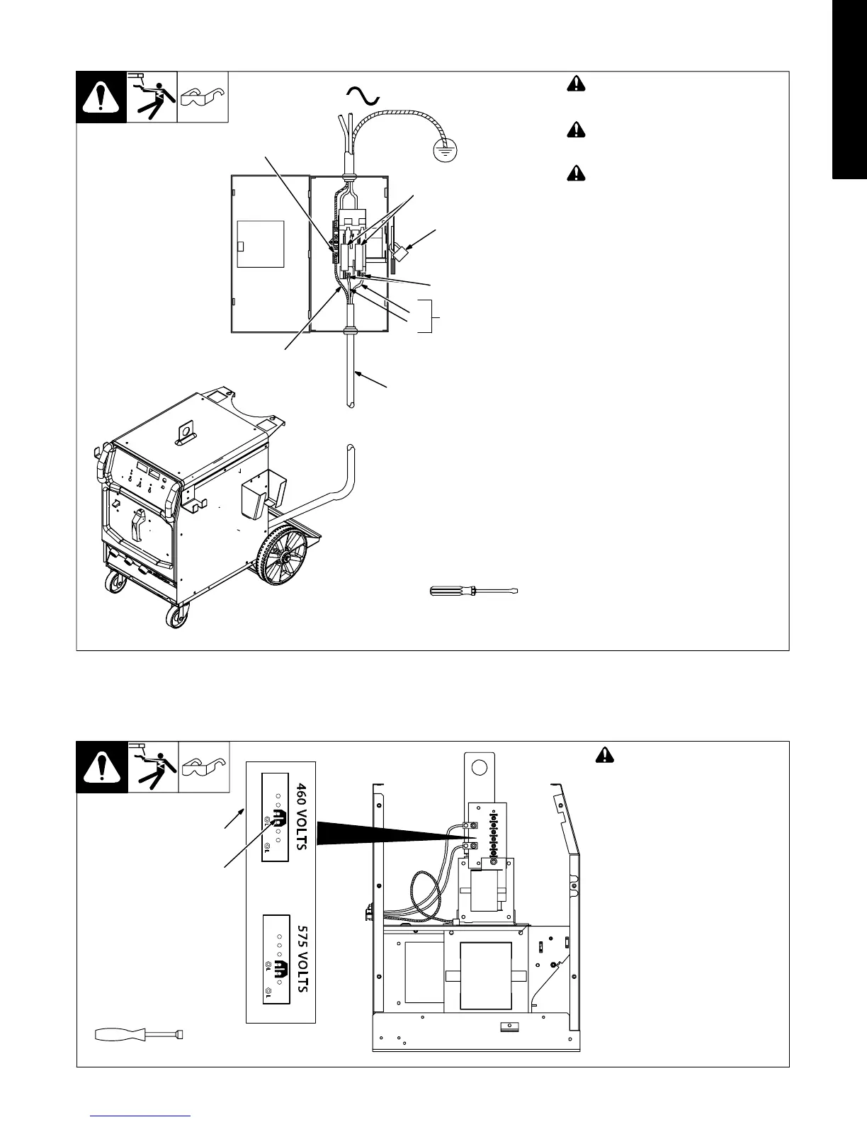
2-16. Connecting Input Power In 208-230 Volt Models
Tools Needed:
L1
L2
804 234-C / Ref. 803 766-B
1
=GND/PE Earth Ground
! Installation must meet all National
and Local Codes − have only quali-
fied persons make this installation.
! Disconnect and lockout/tagout in-
put power before connecting input
conductors from unit.
! Always connect green or green/
yellow conductor to supply
grounding terminal first, and never
to a line terminal.
1 Black And White Input Conductor
(L1 And L2)
2 Green Or Green/Yellow Grounding
Conductor
3 Input Power Cord.
4 Disconnect Device (switch shown in
the OFF position)
5 Disconnect Device Grounding
Terminal
6 Disconnect Device Line Terminals
Connect green or green/yellow grounding
conductor to disconnect device grounding
terminal first.
Connect input conductors L1 and L2 to
disconnect device line terminals.
7 Over-Current Protection
Select type and size of over-current
protection using Section 2-15 (fused dis-
connect switch shown).
Close and secure door on disconnect
device. Remove lockout/tagout device,
and place switch in the On position.
1
2
5
3
7
6
4
‘
2-17. Connecting Input Power In 460/575 Volt Models
A. Placing Jumper Links
Ref. 804 470-B
! Disconnect and lockout/tag-
out input power before
installing or moving jumper
links.
Check input voltage available at
site.
Remove cover and left side panel.
1 Jumper Link Label
2 Jumper Links
Move jumper links to match input
voltage.
Install left side panel and cover, or
go on to Section B.
Tools Needed:
3/8 in
1
2