OM-284794 Page 14
F
Complete Parts List is available at www.MillerWelds.com
SECTION 4 – SPECIFICATIONS
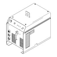
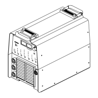
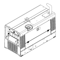
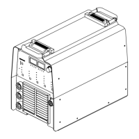
4-1. Serial Number And Rating Label Location
The serial number and rating information for the power source is located on the rear of the machine. Use the rating labels to determine input
power requirements and/or rated output. For future reference, write serial number in space provided on back cover of this manual.
4-2. Software Licensing Agreement
The End User License Agreement and any third-party notices and terms and conditions pertaining to third-party software can be found at
https://www.millerwelds.com/eula and are incorporated by reference herein.
4-3. Information About Default Weld Parameters And Settings
NOTICE – Each welding application is unique. Although certain Miller Electric products are designed to determine and default to certain typical
welding parameters and settings based upon specific and relatively limited application variables input by the end user, such default settings are
for reference purposes only; and final weld results can be affected by other variables and application-specific circumstances. The appropriate-
ness of all parameters and settings should be evaluated and modified by the end user as necessary based upon application-specific require-
ments. The end user is solely responsible for selection and coordination of appropriate equipment, adoption or adjustment of default weld
parameters and settings, and ultimate quality and durability of all resultant welds. Miller Electric expressly disclaims any and all implied warran-
ties including any implied warranty of fitness for a particular purpose.
4-4. Welding Power Source Specifications
F
This equipment will deliver rated output at an ambient air temperature up to 104° F ( 40° C).
F
Do not use information in unit specifications table to determine electrical service requirements. See Sections 5-6, 5-7 and 5-8 for informa-
tion on connecting input power.
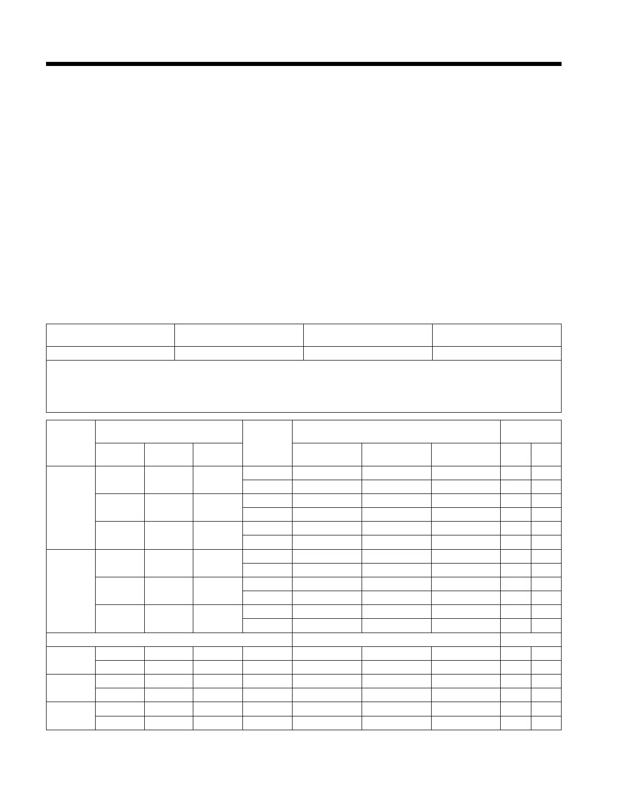
Welding Amperage Range Max Open-Circuit Voltage
(U
0
)
Low Open-Circuit Voltage
(U
0
)
Rated Peak Striking Voltage
(U
p
)
5-300
1
60 8-15
2
14KV
3
1
Welding range for Stick process is 5-230 amperes. For TIG, the amperage range is tungsten diameter dependent (see Section ).
2
Low open-circuit voltage while in TIG Lift Arc
™
, or while in Stick with low open-circuit voltage selected.
3
Arc starting device is designed for manual guided operations.
Process
Output Ratings
Phase
Current Draw (A) At Rated
Input Voltages (V)
Input Power
Current
(A)
Voltage
(V)
Duty
Cycle
208V 240V 480V kW kVA
STICK
230 28.4 30%
1 44 37 18 8.8 9
3 25 22 11 8.6 8.9
160 26.4 60%
1 27 24 12 5.5 5.7
3 16 14 7 5.5 5.7
125 25 100%
1 20 18 9 4.1 4.2
3 12 11 5 4.2 4.3
TIG*
300 22 30%
1 47 41 19 9.4 9.7
3 27 23 11 9.2 9.7
210 18.4 60%
1 27 24 12 5.5 5.7
3 16 14 7 5.5 5.9
175 17 100%
1 22 19 9 4.1 4.2
3 13 11 6 4.3 4.8
Power Draw (W)
Idle OCV
0 60 — 1 90 89 116 — —
0 60 — 3 94 94 131 — —
Idle w/
Output Off
— — — 1 29 30 63 — —
— — — 3 31 34 64 — —
Idle Cooler
On
— — — 1 189 211 250 — —
— — — 3 197 221 278 — —
*Includes cooler power draw.