OM-284794 Page 27
SECTION 6 – SYNCROWAVE OPERATION
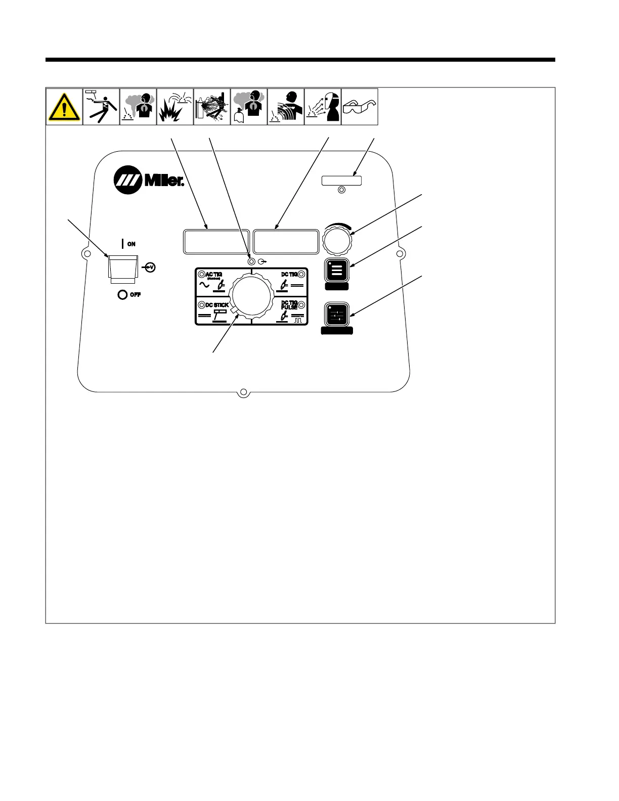
6-1. Syncrowave Controls
MENU
PRO-SET
280539-B
7
2
5
3
8
1
9
6
4
TM
1 Main Power Switch
Use switch to turn machine on or off.
2 Amperage Adjustment Control
Use control to change preset amperage val-
ue. If a remote control is used, preset am-
perage value is the maximum amperage
output available. This control also functions
as a parameter change control while in the
menu mode (see Sections 6-2 thru 7-1).
3 Memory Card Port And Indicator
This port is used to add features to the ma-
chine and update software to the boards
within the machine. Indicator is lit while card
is being accessed (see Section 5-10).
4 Voltmeter
Displays actual rectified average voltage
when voltage is present at the weld output
terminals. It is also used to display parame-
ter descriptions while in the menu.
5 Ammeter
Displays actual amperage while welding and
preset amperage while idle. It is also used to
display parameter selection options while in
the menu.
6 Menu Button
Press button to scroll through available pa-
rameters for the selected process. Hold but-
ton to enter set-up mode (see Sections 6-2
thru 7-1).
7 Output ON Indicator
Blue indicator illuminates when output is on.
8 Process Selector Control
Use to select one of the following
processes:
l AC TIG - Used for welding aluminum.
l DC TIG - (DCEN) Used for welding mild
and stainless steel.
l DC Stick - (DCEP) Used for welding
steels.
l DC TIG PULSE - (DCEN) Used for
welding mild and stainless steel.
9 Pro Set Button
Press button to lock in all parameters to fac-
tory setting while LED is lit. Press and Hold
for 5 seconds to reset all parameters to fac-
tory settings. Meter display counts down.