OM-284794 Page 23
F
Complete Parts List is available at www.MillerWelds.com
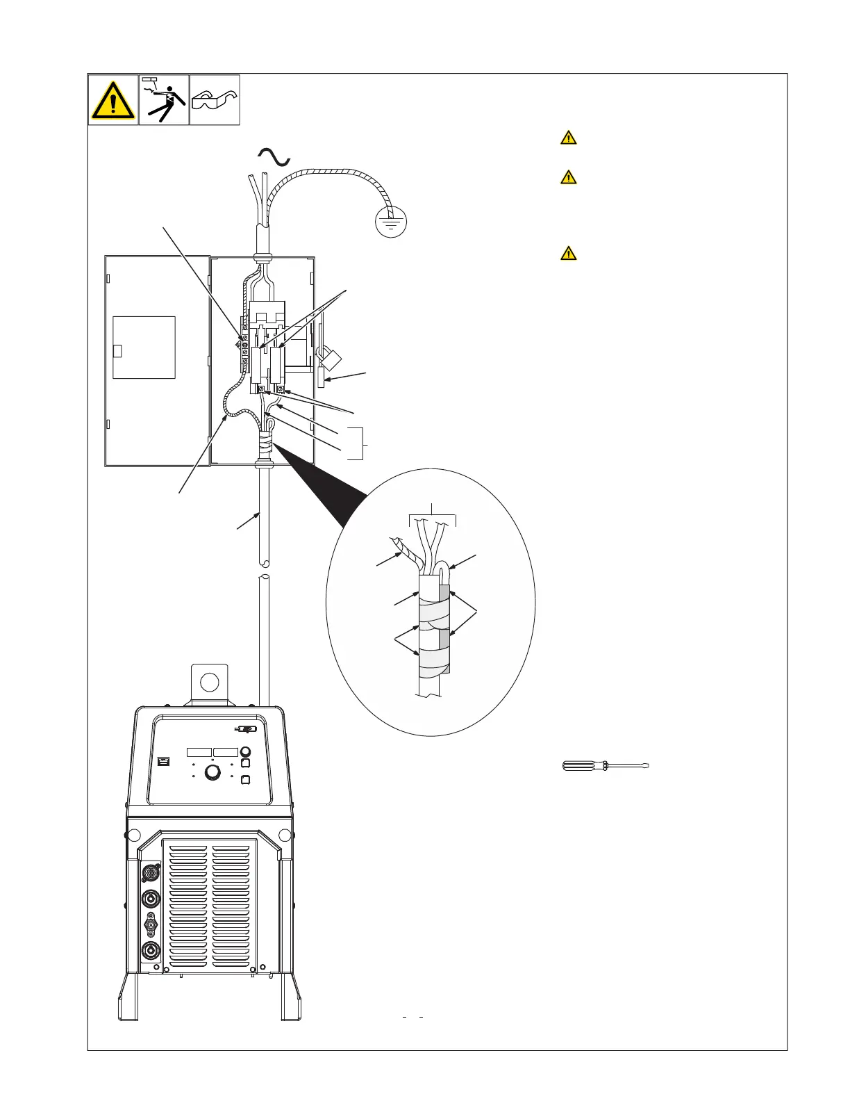
5-7. Connecting 1-Phase Input Power
1
4
2
7
6
L1
L2
1
= GND/PE Earth Ground
3
3
1
8
10
input1 2012 05 803766-C / Ref. 805618-A
6
5
9
Installation must meet all National
and Local Codes—have only quali-
fied persons make this installation.
Disconnect and lockout/tagout in-
put power before connecting input
conductors from unit. Follow es-
tablished procedures regarding
the installation and removal of
lockout/tagout devices.
Always connect green or green/
yellow conductor to supply
grounding terminal first, and never
to a line terminal.
See rating label on unit and check input volt-
age available at site.
1 Black And White Input Conductor (L1
And L2)
2 Red Input Conductor
3 Green Or Green/Yellow Grounding
Conductor
4 Insulation Sleeving
5 Electrical Tape
Insulate and isolate red conductor as shown.
6 Input Power Cord
7 Disconnect Device (switch shown in the
OFF position)
8 Disconnect Device Grounding Terminal
9 Disconnect Device Line Terminals
Connect green or green/yellow grounding
conductor to disconnect device grounding
terminal first.
Connect input conductors L1 and L2 to dis-
connect device line terminals.
10 Over-Current Protection
Select type and size of over-current protec-
tion using Electrical Service Guide (fused
disconnect switch shown).
Close and secure door on disconnect device.
Follow established lockout/tagout proce-
dures to put unit in service.
OM-222 Page 1
allen_wrench
NGO’s
tools/
flathead philips head wrench
pliers
knife
heavy-duty workclamp light-duty workclamp wirecutter frontcutter
allen_set
needlenose
steelbrush nutdriver
chippinghammer
solderiron
stripcrimp
drill
torque wrench
socket wrench
hammer awl file
crimper
paintbrush
feelergauge flashlight ruler
toothbrush
greasegun
qtip (swab)
vicegrip
handream
punch
filterwrench
strapwrench
airgun
solvent pinextractor eprompuller pipewrench
torque screwdriver
cr
escent wrench