OM-284794 Page 18
F
Complete Parts List is available at www.MillerWelds.com
SECTION 5 – INSTALLATION
5-1. Selecting A Location
Movement
A complete Parts List is available at www.MillerWelds.com
OM-
Writers: Remember to move unit dimension and weight and rating la-
bel location information to the appropriate sections.
1-3. Selecting A Location
3
18 in.
(460 mm)
18 in.
(460 mm)
1
2
loc_large 2018-08
A complete Parts List is available at www.MillerWelds.com
OM-
Writers: Remember to move unit dimension and weight and rating la-
bel location information to the appropriate sections.
1-3. Selecting A Location
3
18 in.
(460 mm)
18 in.
(460 mm)
1
2
loc_large 2018-08
Location And Airflow
4
3
18 in. (460 mm)
18 in. (460 mm)
18 in. (460 mm)
18 in. (460 mm)
3
18 in.
(460 mm)
18 in.
(460 mm)
1
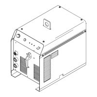
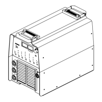
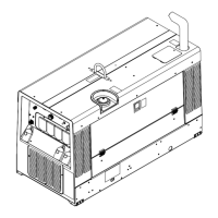
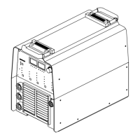
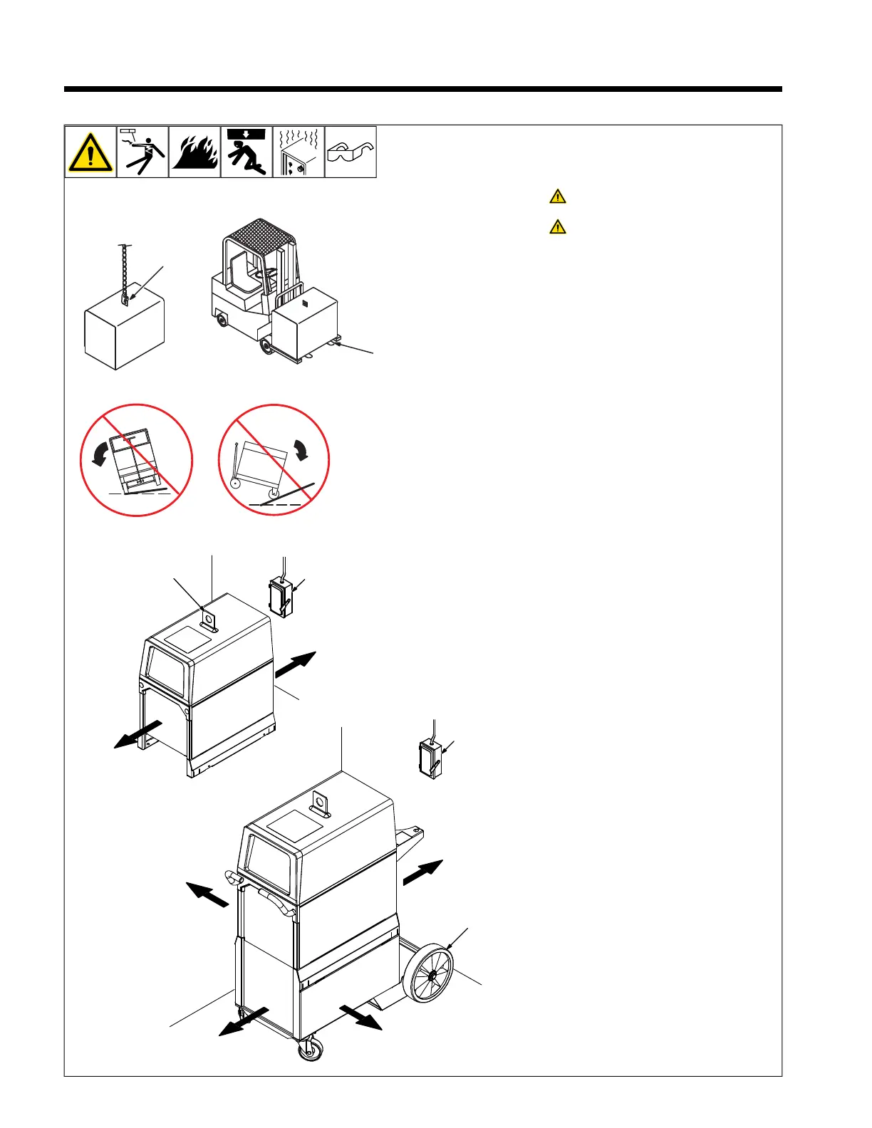
Do not move or operate unit where
it could tip.
Special installation may be re-
quired where gasoline or volatile
liquids are present - see NEC Ar-
ticle 511 or CEC Section 20.
1 Lifting Eye
2 Lifting Forks
Use lifting eye or lifting forks to move unit.
If using lifting forks, extend forks beyond op-
posite side of unit.
3 Line Disconnect Device
4 Running Gear
Locate unit near correct input power supply.