A5/A3™ Service Manual 046-001141-00 2 - 15
Installation Guide Assembly
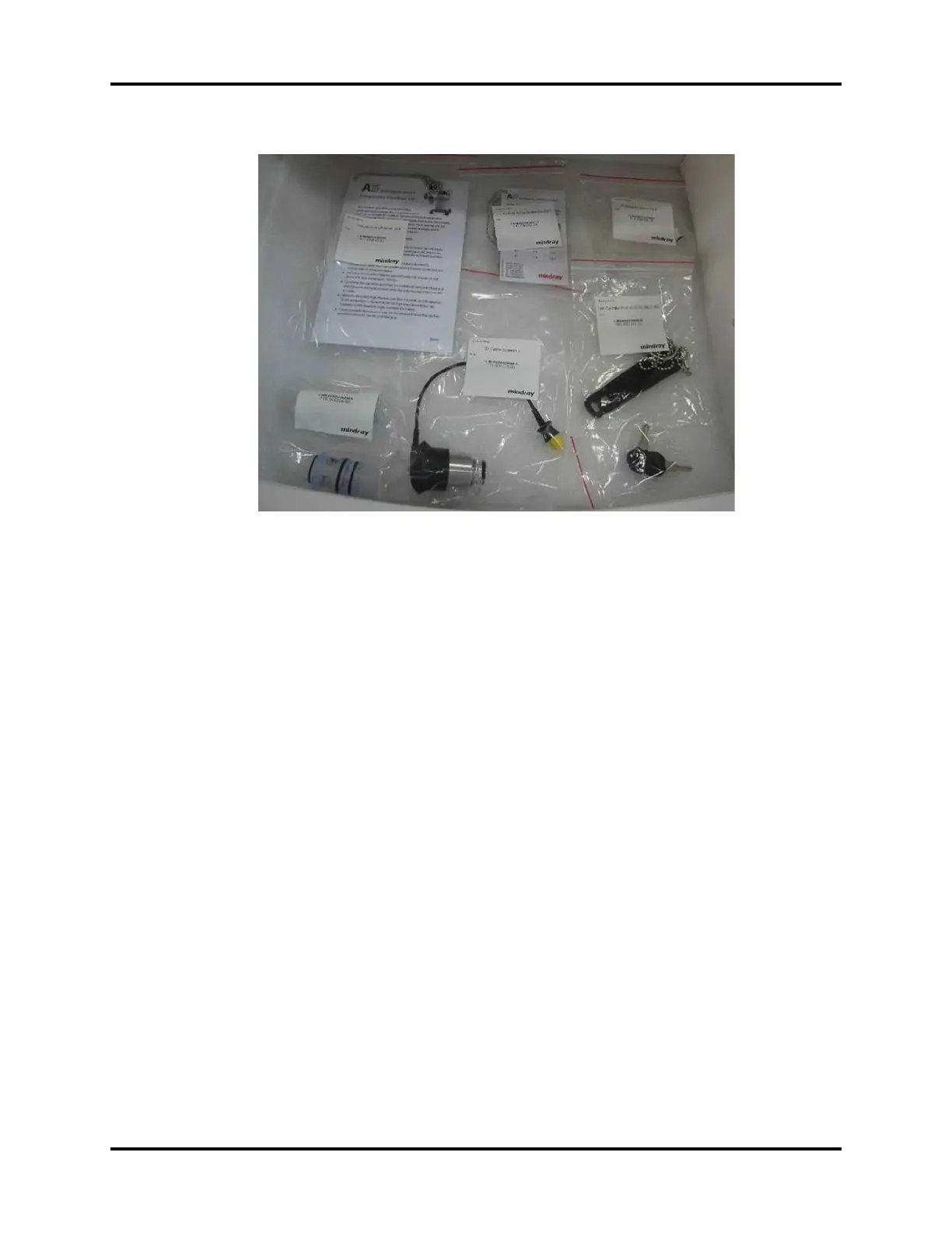
FIGURE 2-23
27. Open the rear panel and unscrew the thumbscrews to open the battery compartment. Install
one or two batteries with the proper polarity. Close the compartment and tighten the
thumbscrews.
28. On the back of the unit, verify the order of the cylinder yokes are from left to right: O2, Air, and
N2O.
29. Verify the order of the pipeline fittings are from top to bottom: N2O, Air, and O2.
30. Install the tank washers.
31. Install the gas cylinders. Ensure that the cylinders are secured to their matching cylinder supply
connections, which are labeled “O2,” “Air,” and “N2O.”
32. Connect each gas supply by connecting the hose connectors to the gas supply sockets (DISS
type). Turn the connectors clockwise to fasten them securely to the sockets. Verify that the
pressure of the gas supply is within the specifications of the machine.
33. Connect a manual ventilation bag (supplied by the user) to the bag arm on the breathing
system.
34. Connect a patient breathing circuit (supplied by the user) to the inspiratory and expiratory
connections.
WARNING: Use breathing circuits and manual bags in accordance with ASTM F1208
and compatible with standard 22mm male conical fittings per ASTM
specifications F 1054.
35. Connect the hose from the gas scavenger to the operating room's EVAC connector. At the AGSS
tank, turn the knob on top of the scavenger until the float is between the Min and Max
markings.