Assembly Installation Guide
2 - 16 046-001141-00 A5/A3™ Service Manual
NOTE: The knob on the top of the scavenger is meant to adjust the flow from
the EVAC. When the knob is fully closed it does not need to completely
shut off flow.
36. (A5 with AG module only) Install the O2 Sensor Cover Assebly (P/N: 115-016523-00).
37. (A3s and A5s without AG module only) Install the oxygen sensor (from Topfill) into the stainless
steel housing. The O2 Cell should be tightened only enough to compress the o-ring about a 1/4
turn.
38. (A3s and A5s without AG module only) Screw the O2 Cable housing onto the stainless steel
housing until it is snug. Do not overtighten.
39. (A3s and A5s without AG module only) Connect the oxygen sensor external cable between the
oxygen sensor and the side of the A5/A3, aligning the yellow marks on the cable and connector.
40. Plug the mains cable into a grounded socket. Power up the A5/A3 by turning the main power
switch (located on the front of the A5/A3) to the ON position. Wait until the LCD display provides
information about the leak test. Observe that the start-up self-test is successful. Do not connect,
disconnect or move the breathing circuits or breathing bags while the self-test is in process.
41. Mount the monitors and arms per instructions in the monitoring kit.
WARNING: Use only Mindray-approved monitors and arms with the A5/A3.
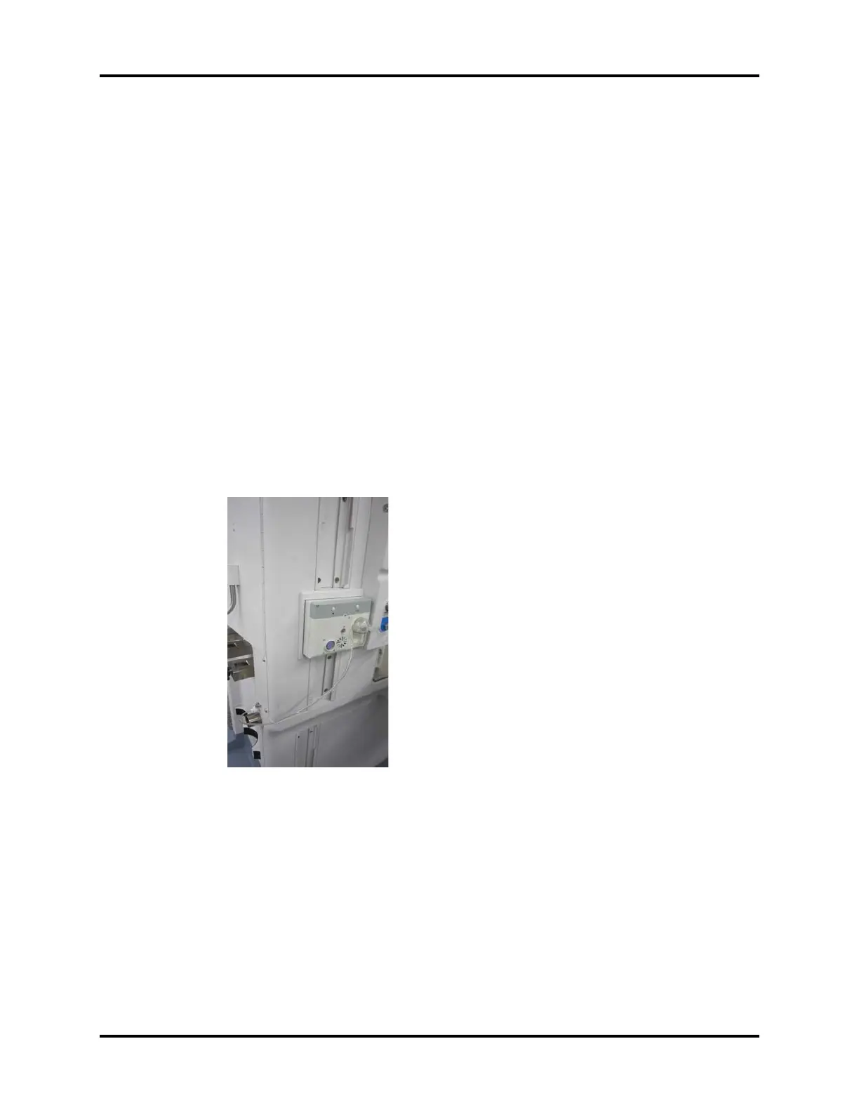
42. Install the gas module into the module rack on the left side of the unit.
FIGURE 2-24
43. Connect Hose (P/N: 801-0631-00078-00 or P/N: 115-008426-00) to the outlet of the gas module
and to the Colder fitting at the back of the A5/A3. Place the unused hose in the bottom drawer.
44. Place the following parts into the bottom drawer:
• A5/A3 Operating Instructions (P/N: 046-003777-00)
• A5/A3 Anomalies List (P/N: 046-001764-00)
• Washer, Seal (P/N: 0348-00-0185)