Hardware
1.7 Driving Board
The driving board controls and drives the pumps, valves, and motors.
1.7.1 Basic Functions
The driving board drives the valves, pumps and motors. It carries out the
following instructions sent by the CPU: to open/close the pumps or solenoid
valves; to control the motors of the syringes; to control the movement of the
sample probe; to remain the torques of the motors when the analyzer has
entered the screen saver.
1.7.2 Basic Blocks
The driving board mainly consists of a power block, switching block and motor
control block. See the figure below for the positions of each block of the PCBA.
1.7.2.1 Power block
The power block includes a 5V, 12V and 30V DC supply. The 12V and 30V
supply comes from the power interfaces, where two LEDs are installed to
respectively indicate the whether the 12V or 30V supply is connected. When
the LED is on, it indicates the corresponding power has been connected to the
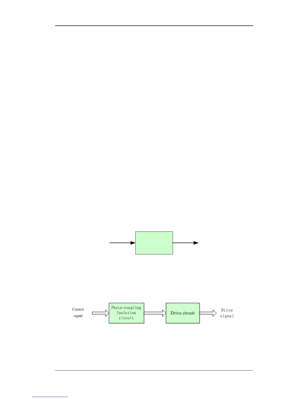
driving board. The MC7805T converts the received 12V supply into the 5V
supply, as the following figure shows.
MC7805T
12V
5V
Figure 1-7 How the 5V power is obtained
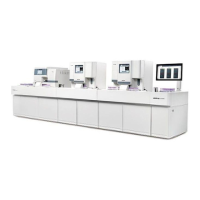
1.7.2.2 Switching block
The switching block mainly consists the photocoupling circuit and driving circuit of the pumps
and valves, as the figure below shows.
Figure 1-8 Switching control circuit
1. Photocoupling circuit
The photocoupling circuit mainly consists of the photocoupler and resistors. It
provides 16 TTL outputs to the valves and pumps. The photocoupler, TLP521-2,
BC-2800 Auto Hematology Analyzer (V1.0) 1- 11