EasyManuals Logo

Mindray DC-30 Service Manual

Mindray DC-30
213 pages
To Next Page IconTo Next Page
To Previous Page IconTo Previous Page
Page #142 background imageLoading...
Page #142 background image
7-42 Structure and Assembly/Disassembly
Figure 7-41 Knob and TGC slider position
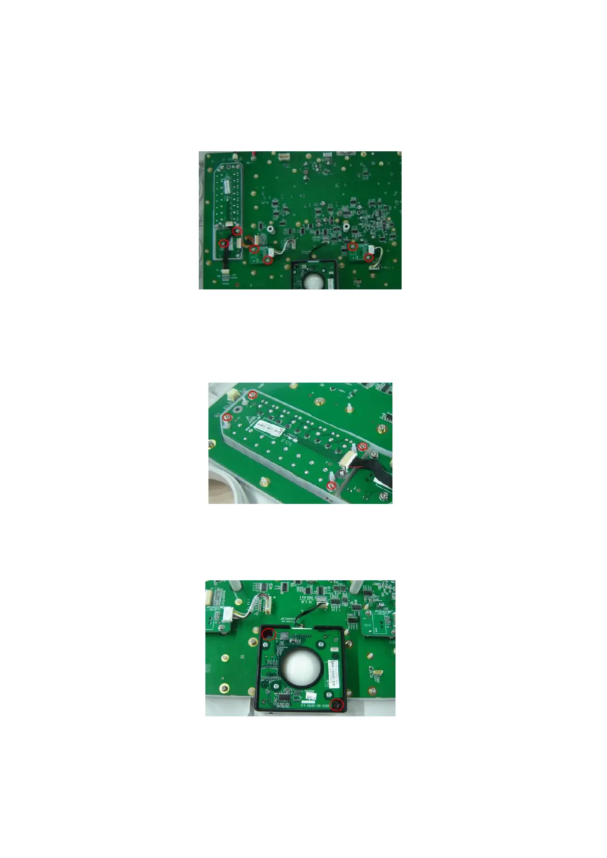
2. Pull out the connecting cable plug, remove the M3X8 fixing screws (6 pcs) as shown
in the figure, and two single-encoder board and a dual-encoder board can be
disassembled.
Fig 7-42 Disassemble the Encoder Board
7.4.10.2 TGC Board
1. Pull out the TGC rod caps, refer to the 7.4.10.1 Single/dual-encoder Board chapter.
2. Pull out the connecting cable plug, remove the M3X8 screws (4 pcs) fixing the board
as shown in the figure to disassemble the TGC board.
Fig 7-43 Disassembly of the TGC board
7.4.10.3 Trackball
Pull out the connecting cable plug of trackball, remove the M3X8 screws (2 pcs)
which are used to secure the trackball, and take out the trackball.
Fig 7-44 Disassembly of the trackball

Table of Contents

Questions and Answers:

Question and Answer IconNeed help?

Do you have a question about the Mindray DC-30 and is the answer not in the manual?

Mindray DC-30 Specifications

General IconGeneral
DICOMYes
Hard Drive500 GB
Continuous Wave DopplerYes
Tissue Harmonic ImagingYes
Relative Humidity30% to 85% (non-condensing)
Imaging ModesColor Doppler, Power Doppler
Power Supply100-240 V~ 50/60 Hz
Probe Connectors2 active probe connectors
Probe TypesConvex, Linear, Phased Array
Operating Temperature10°C to 40°C
Storage Temperature-20°C to +55°C
Transducer Ports2

Related product manuals