Structure and Assembly/Disassembly 7-43
7.4.10.4 Keyboard Top Cover Assembly
1. Remove the single/dual-encoder board (refer to 7.4.10.1 chapter).
2. Take out the TGC board (refer to 7.4.10.2 chapter).
3. Take out the trackball assembly (refer to 7.4.10.3 chapter).
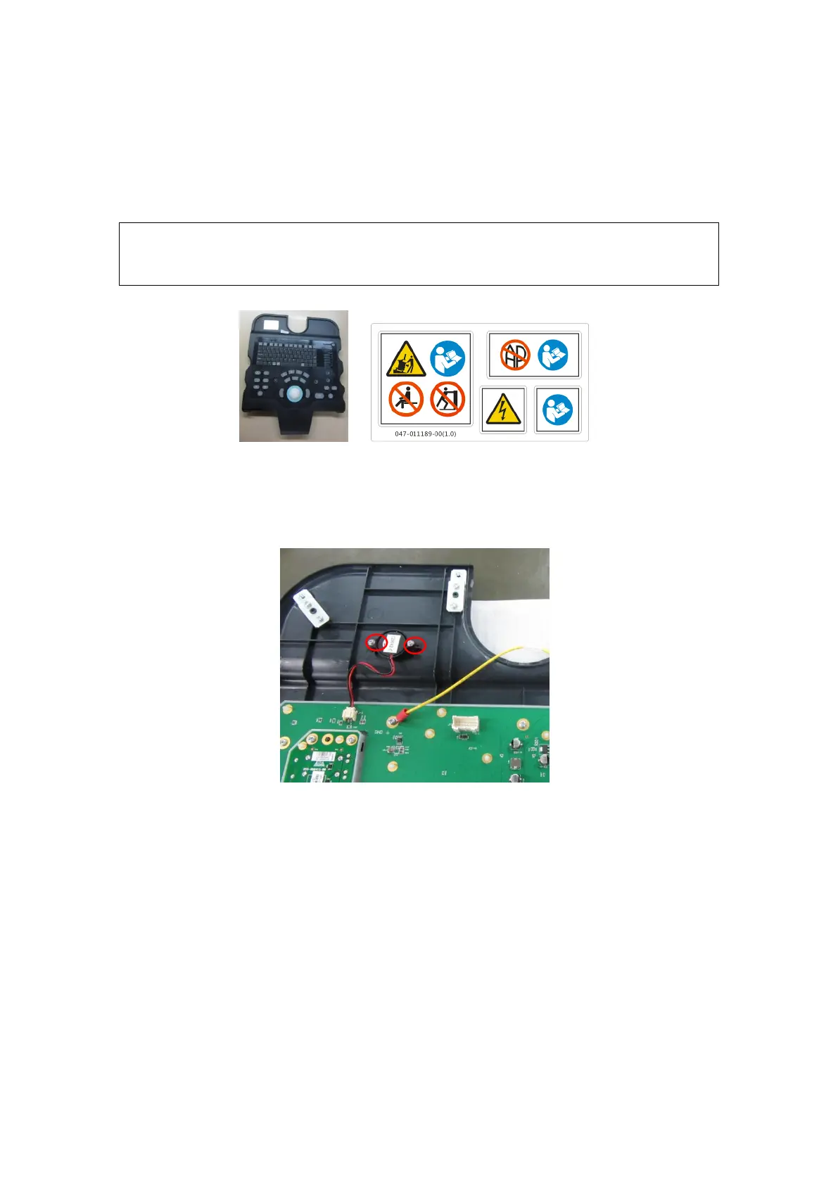
4. The residual parts are keyboard top cover assembly, as shown in the following.
IF you need to replace Keyboard Top Cover Assembly, please refer to the
previous assembly, and select the corresponding label. Then, stick it to the
monitor assembly.
Fig 7-45 Keyboard Top cover assembly and labels
7.4.10.5 Buzzer
Pull out the connecting cable plug; remove the fixing PT2X8 screws (2 pcs) as
shown in the figure to disassemble the buzzer.
Fig 7-46 Disassembly of the buzzer
7.4.10.6 USB Adapter Board
Remove the PT3X8 self-tapping screws (2 pcs) which are used to secure the USB
adapter board, and then remove the board.