6 - 38 Operator’s Manual
6 Image Acquisition
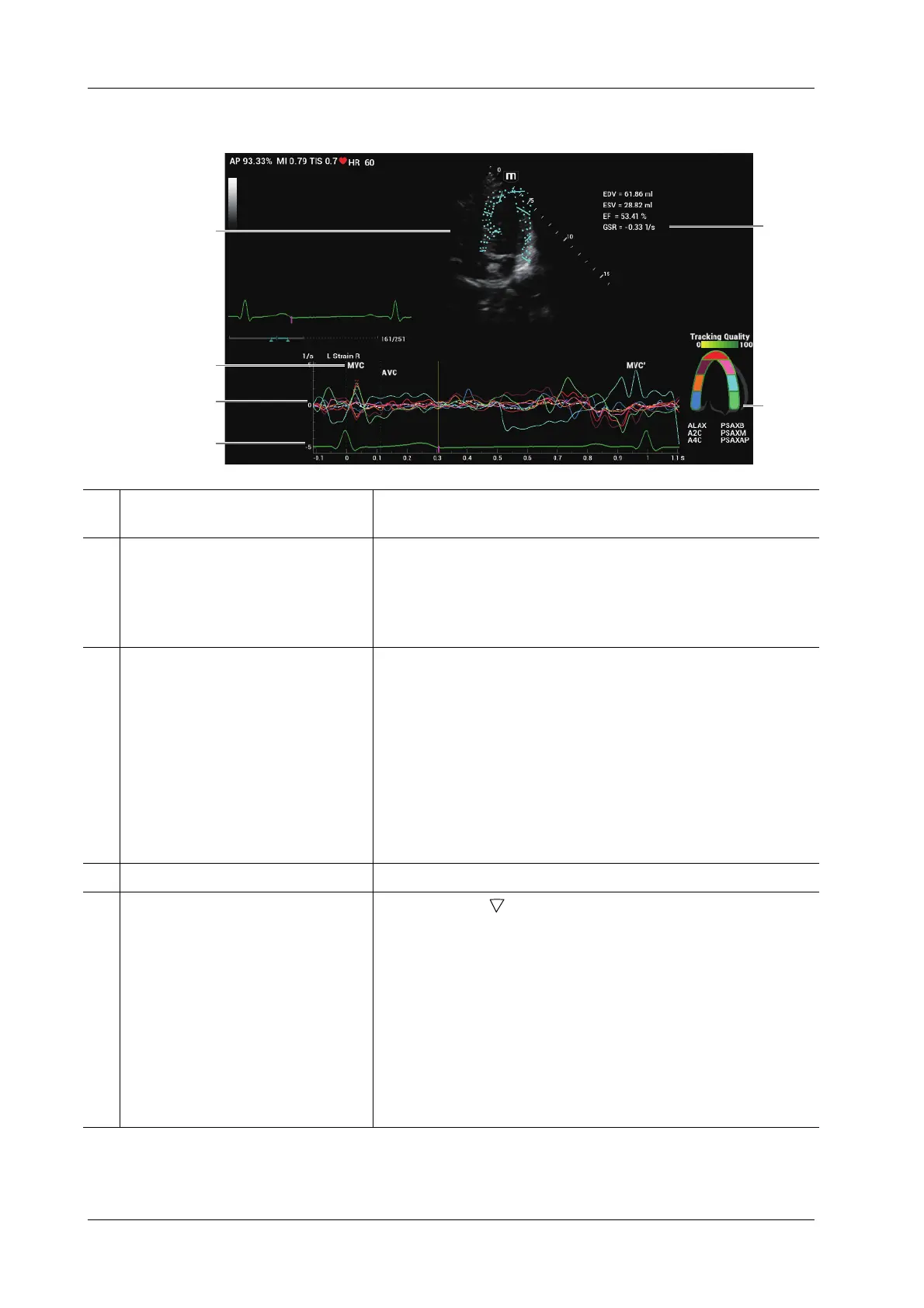
6.20.2 Screen Display of Smart TTQA
6
1
2
3
4
5
1 Displays image used to generate trace
curve
/
2 Displays corresponding time of AVO
(aortic valve open)/AVC (aortic valve
close)/MVO (mitral valve open)/
MVC (mitral valve close).
/
3 Display curve: Velocity/
Displacement/Strain/Strain Rate.
Each curve on the image is matched with a certain segment in the
cardiac segmentation model (6), identified by different colors.
• Velocity curve: X-axis represents time (s); Y-axis represents
velocity (cm/s).
• Displacement curve: X-axis represents time (s); Y-axis
represents displacement (mm).
• Strain curve: X-axis represents time (s); Y-axis represents
deformation of the tissue (%).
• Strain-rate curve: X-axis represents time (s); Y-axis represents
strain by time (s
-1
).
4 Displays ECG trace /
5 Displays cardiac segmentation
model, and each segment name is
illustrated beneath the model.
• In the figure, marks the peak position of the curve.
• Under tracking status, click on a segment in the cardiac
segmentation model. The segment has “X” mark and its
corresponding calculating is eliminated.
• Tap certain segment in the cardiac segmentation model, the
segment will turns grey and its corresponding curve no longer
displays.
• You can get the current X/Y axis value by moving the cursor
onto one point on the curve; and if you tap at this time, the
frame marker will move to the spot.
The segment boundary color indicates the tracking quality.