5. Product presentation
MiR100 User guide (en) 09/2019 - v.1.4 ©Copyright 2019: Mobile Industrial Robots A/S. 38
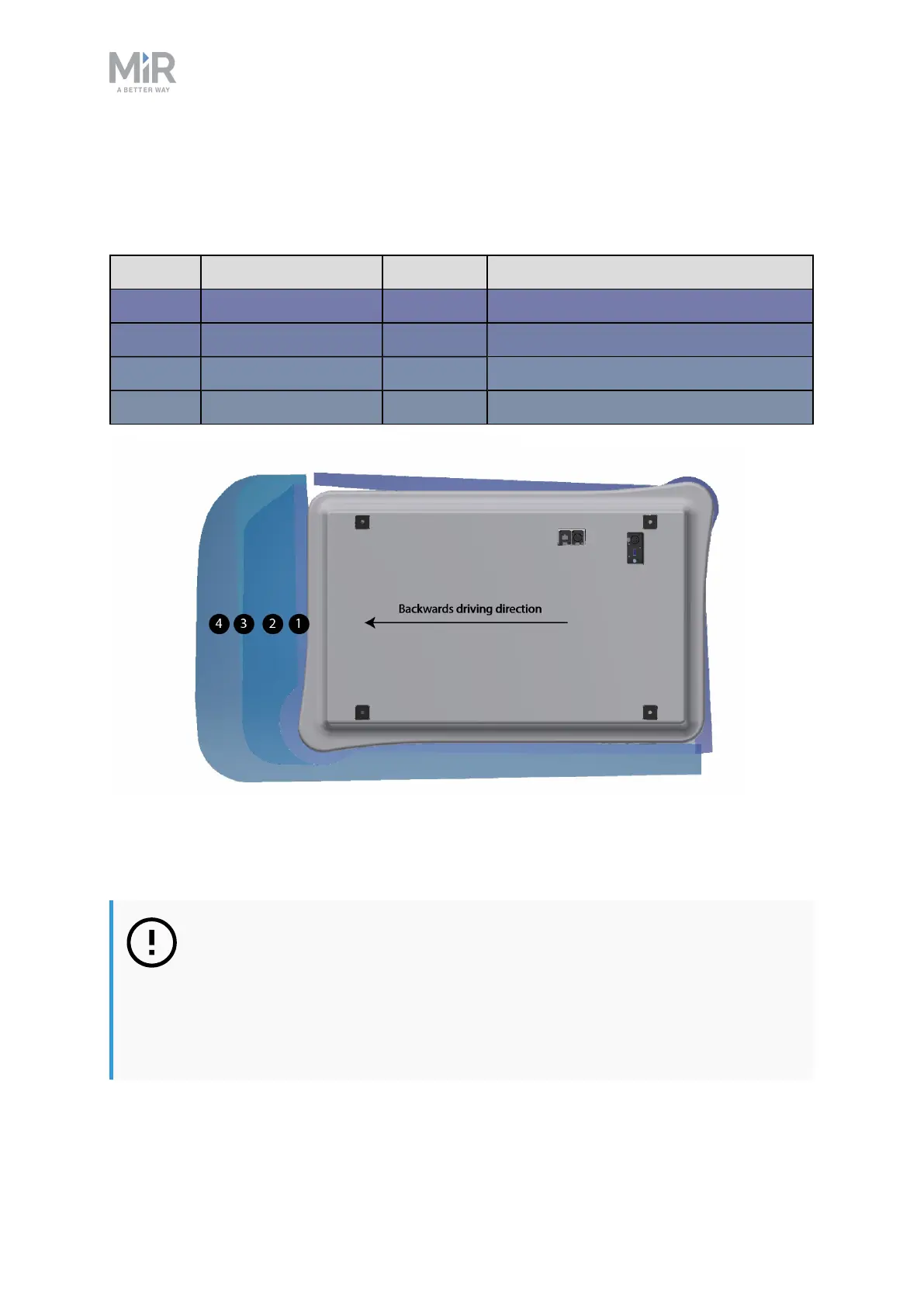
Field sets for backwards driving direction
This table shows speeds and field sets in backwards driving direction. The colors correspond
to the field set shown in the illustration below.
Case Speed Field set Comments
1 -1.14 to 1.80 m/s 30 mm Reversing and slowly backwards
2 -0.20 to 0.15 m/s 120 mm
3 0.40 to 0.21 m/s 290 mm
4 -1.50 to 0.41 m/s 430 mm Backwards at max. speed
The illustration shows the field set contours in backwards driving direction. The reach of the
field set changes with the robot's speed. The illustration also shows how the front scanner
reduces its protective field sets to a minimum when the robot moves backwards.
NOTICE
Protective field tolerances
Scanners measure distances to diffuse reflections which means that a
tolerance is added to the protective field sets to secure a safe detection of
persons crossing the protective field sets. The tolerance distance is 100 mm.