Mitel 3000
Installation & Maintenance Manual
33
Connecting the extensions
It is recommended that all extensions be cabled with two pairs. The Feature Phones use all four wires and
standard phones use the AB pair only.
Do not exceed the following resistance or distance limits when connecting extensions to the System Unit. (The
distances listed assume 24 AWG tinned copper conductor is used.)
• 100 Ohms, or 1600 feet, for Feature Phones
• 400 Ohms, or 6500 feet, for a standard telephone
The extension cables must be of twisted-pair construction, using 24 AWG wire.
All extensions should connect into standard line jack units. Extension cabling
should not be exposed to high voltage surges, (for example, surges induced by
lightning or neighboring high current-carrying cables). If this is a possibility,
external protection of the CCU and extensions using earthed line surge
protectors is essential.
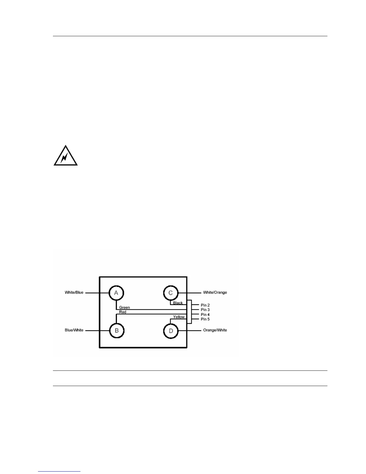
Wiring Jacks
The cabling to standard Jacks for the Feature Phones is as follows: -
W/BL to Connector A (Speech) Pin 3 on RJ11
BL/W to Connector B (Speech) Pin 4 on RJ11
W/O to Connector C (DATA) Pin 2 on RJ11
O/W to Connector D (DATA) Pin 5 on RJ11
The cabling for standard analog sets uses the speech pair A, B only.
NOTE: If there is no audio on the Feature Phone but the display is working this indicates that the speech pair is
open. If there is no audio and no display this indicates the CD is open.