Installation
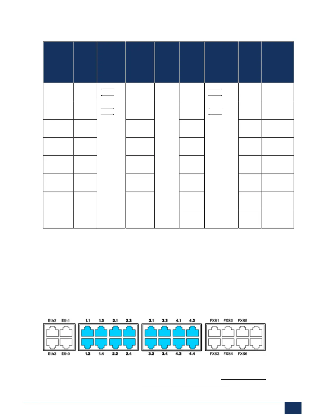
Table 42: Cabling for primary rate interface, PRI, networked with leased-line or dial-up connection
RJ45Pin PRI
PINX 1
signal
Cable
cores,
straight
patch
cable
PRI
signal
NT1
Network PRI
signal
NT1
Cable cores
Straight
patch cable
PRI
PINX 2
signal
RJ45Pin
1 RxA RxA RxA RxA 1
2 RxB RxB RxB RxB 2
3 — — 3
4 TxA TxA TxA TxA 4
5 TxB TxB TxB TxB 5
6 — — 6
7 — — 7
8 — — 8
See also:
System Manual “PISN / QSIG Networking”
4.7.2.3 FXO network interfaces
With the appropriate interface cards and wiring adapters, FXO network interfaces can be made available at
RJ45 sockets 1.x...4.x. The possible RJ45 sockets are highlighted in colour in the figure below.
Figure 34: Connection possibilities for FXO network interfaces
On cards with 16 interfaces RJ45 sockets 9 to 16 are multiply assigned. The signals can be split again to
individual RJ45 sockets using patch cables and the fan-out panel FOP (see Fan-out panel FOP) or with 8-
fold assigned connecting cables (see e.g. Prefabricated system cable 4 x RJ45).
Release 7.1
System Manual for Mitel SMB Controller 120
 Loading...