Installation
5. Connect the earthing (see Connecting the earthing wire).
6. Fit the housing cover.
7. Secure the cage nuts in the appropriate positions in the rack’s fastening rails (see Rack-mounting on
page 91).
8. Secure the communication server to the rack’s fastening rails using the M6 screws, the plastic washers
and the cage nuts.
9. Fasten the snap-on tag to the front panel.
10. Reconnect the communication server to the power supply.
4.2.6.2 Installing the cable cover
Materials required:
• Cable cover set
• Screwdriver
To install the cable cover proceed as follows:
1. Pull off the screw covers on the left and right of the front panel.
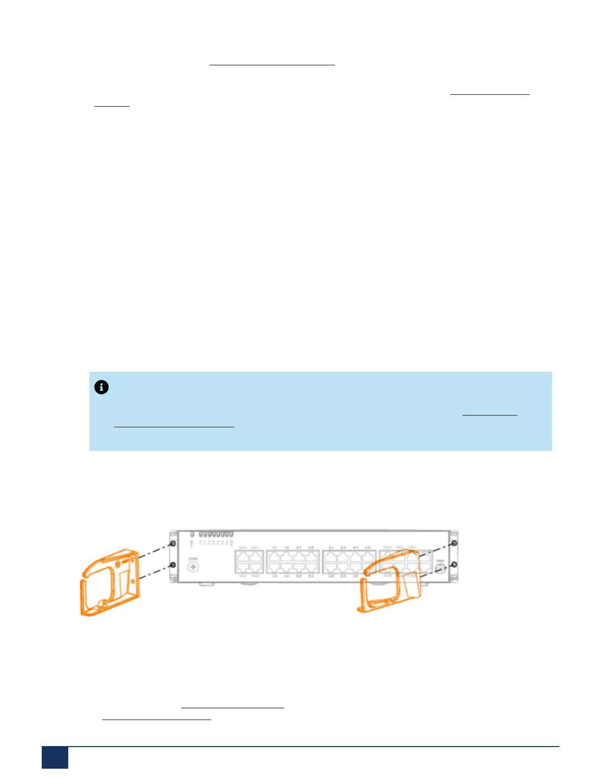
2. Use the M4 screws of the cable cover set to secure the brackets for the cable cover to the
communication server.
Note:
The two brackets are not identical. Compare the cable brackets with the ones in Installing the
brackets for the cable cover.
3. Fit the cable cover over the brackets from above until they are felt to engage.
Figure 14: Installing the brackets for the cable cover
4.2.7 Desktop installation
To protect the cable connections the communication server can also be secured using three screws. The
same drilling plan (see Drilling plan on page 88) and the same procedure apply as for wall mounting
(see Wall-mounting procedure).
Release 7.1
93 System Manual for Mitel SMB Controller
 Loading...