Installation
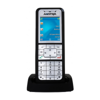
Figure 9: Minimum distances for wall mounting (front panel facing to the right)
All dimensions in mm
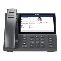
Figure 10: Minimum distances for wall mounting (front panel facing downwards)
All dimensions in mm
4.2.5.2 Drilling plan
The communication server is suspended into two pre-mounted wall screws using the suspension points
in the housing base. Depending on the type of mounting, these are the suspension points marked under
position A or B on the drilling plan. The communication server is secured with a third screw to prevent it
from being dislodged accidentally (position C).
Release 7.1
System Manual for Mitel SMB Controller 88
 Loading...