68P80801E30-A 5/1/2002 4-43
Gen 3 Site Controller System Manual Chapter 4 Installation
Intercabling Connections
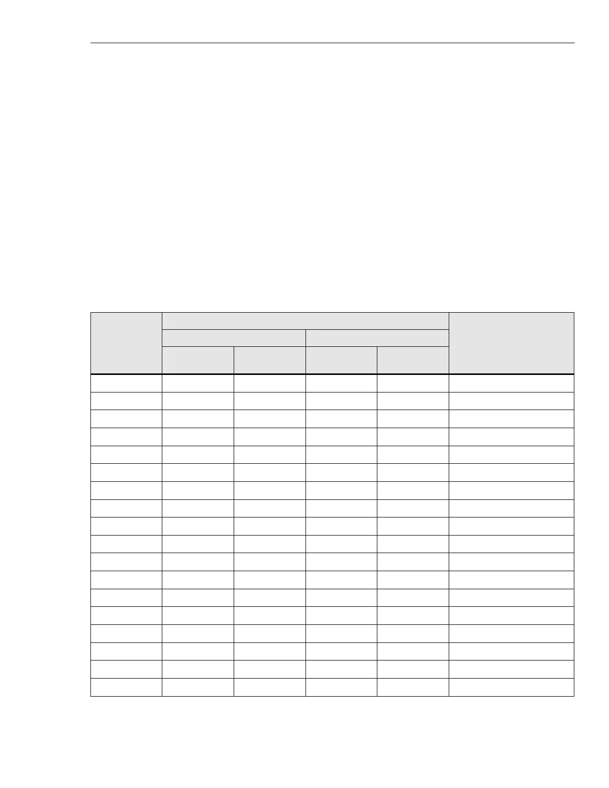
EAS/EAS2 Alarm / Control Connector Pinouts
Typically, USER ALARM / CONTROL and SYSTEM ALARM CONTROL
connectors connect to the site alarm wiring using a punchblock. The tables
that follow list EAS/EAS2 connector pinouts and functions:
• Tables 4-17 and 4-18 show P9 and P10 D-connector pinouts,
respectively.
• Table 4-19 defines pin numbers on connectors P5 through P8.
• Tables 4-20 and 4-21 list user and system relay outputs on
connectors P9 and P10.
• Table 4-22 lists internal relay outputs on connector P5.
Site alarm wiring should be complete before installation.
Table 4-17 User Alarm Inputs
Alarm Code. P9 (USER ALARM / CONTROL) Pin No. Function
EAS (D-SUB 50 CONN.) EAS2 (CHAMP 50 CONN.)
RETURN
Signal (Live)
Connection
RETURN
Signal (Live)
Connection
212 8 7 22 47 customer defined input
213 10 9 21 46 customer defined input
214 12 11 20 45 customer defined input
215 14 13 19 44 customer defined input
216 16 15 18 43 customer defined input
217 18 17 17 42 customer defined input
218 20 19 16 41 customer defined input
252 22 21 15 40 customer defined input
203 24 23 14 39 customer defined input
204 26 25 13 38 customer defined input
205 28 27 12 37 customer defined input
206 30 29 11 36 customer defined input
207 32 31 10 35 customer defined input
208 34 33 9 34 customer defined input
209 36 35 8 33 customer defined input
211 38 37 7 32 customer defined input
201 40 49 6 31 customer defined input
202 42 41 5 30 customer defined input
 Loading...


