Chapter 3 Pre-Installation Gen 3 Site Controller System Manual
Electrical Requirements
3-14 68P80801E30-A 5/1/2002
The positive (+) return lead is grounded at a single point on the rectifier load
return bus. Table 3-2 shows the color coding for these wires.
Cabinet Requirements
Proper sizing of the rectifiers and batteries is accomplished by the iDEN
System Manager when the site controller is ordered. The information in
Table 3-3 is provided for customers that prefer to design a unique DC power
system. This table lists the power system requirements of the Cabinet.
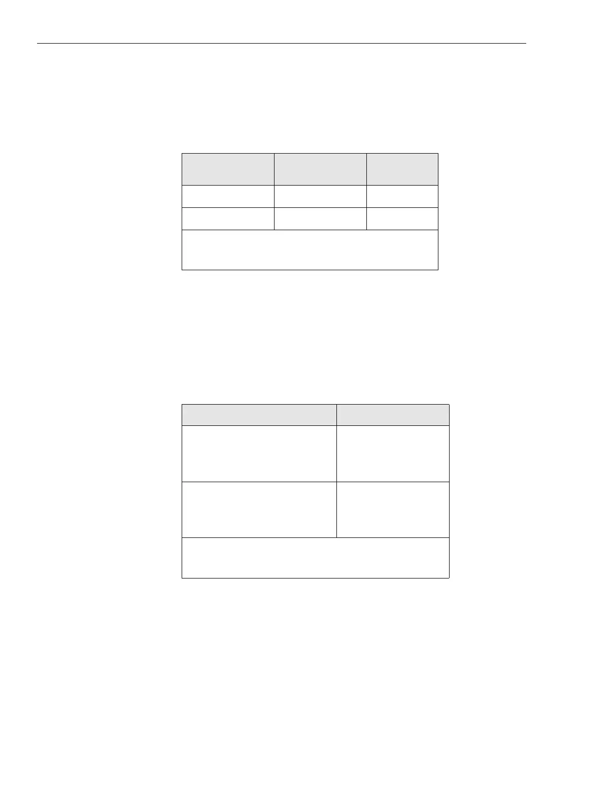
Table 3-2 48Vdc power bus color coding
Description
Battery
connection
Wire
color
-48 Vdc (nominal) negative (-) red
DC return positive (+) black
NOTE:
The hot side is negative polarity (-) in the 48 Vdc
system power bus and the ground side is positive polarity (+).
Table 3-3 Cabinet power system requirements
Configurations Requirement
DC power system: *
minimum
maximum
-40 Vdc
-60 Vdc
Cabinet:
Site Controller
EAS/EAS2
40 Watts
50 Watts
* Voltage is measured at the circuit breaker panel input of the
equipment cabinets.
 Loading...


