Chapter 4 Installation Gen 3 Site Controller System Manual
Intercabling Connections
4-46 68P80801E30-A 5/1/2002
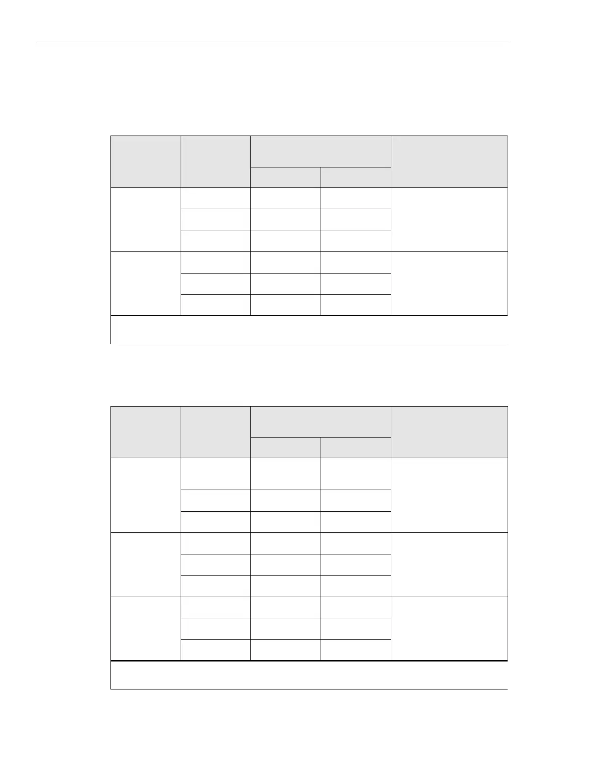
Table 4-20 User Relay Outputs
Alarm Code. Contact
P9 (USER ALARM / CONTROL)
Pin No.
FunctionEAS EAS2
256 COM 45 28 customer defined output
NC 44 4
NO 46 3
255 COM 49 26 customer defined output
NC 48 2
NO 50 1
NOTE:
NC = Normnally Closed; NO = Normally Open.
Table 4-21 System Relay Outputs
Alarm Code. Contact
P10 (SYSTEM ALARM /
CONTROL) Pin No.
FunctionEAS EAS2
248 COM 41 30 customer defined output.
generator remote start
NC 40 6
NO 42 5
254 COM 45 28 reserved for system use
NC 44 4
NO 46 3
253 COM 49 26 reserved for system use
NC 48 2
NO 50 1
NOTE:
NC = Normnally Closed; NO = Normally Open.
 Loading...


