68P80801E30-A 5/1/2002 4-53
Gen 3 Site Controller System Manual Chapter 4 Installation
Intercabling Connections
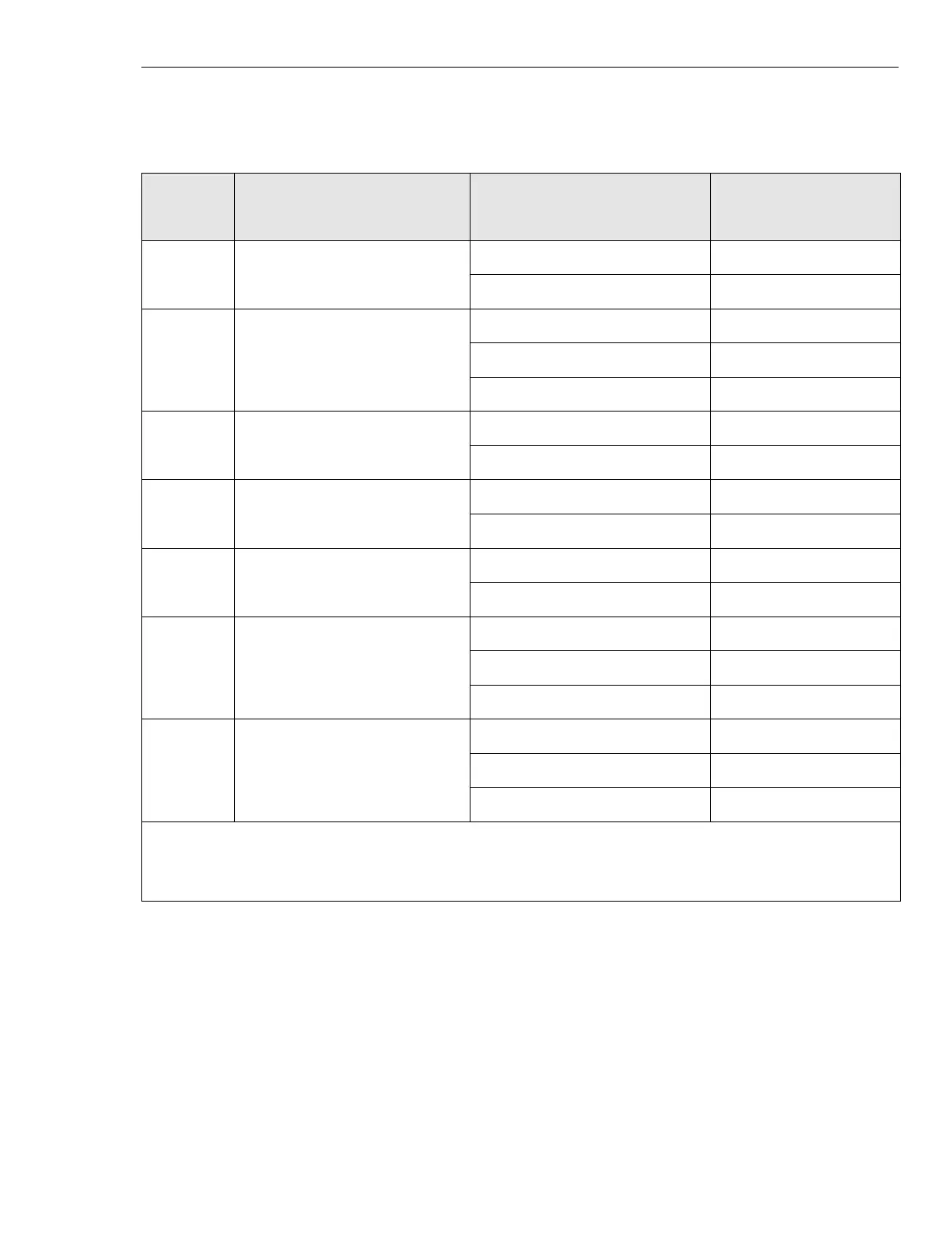
247 Major rectifier failure 17
42
248 Generator remote start 6
5
30
249 RFC #4 combiner/multicoupler
amplifier
27 20
245
250 RFC #4 combiner/multicoupler
power supply
26 19
444
251 RFC #4 tower top amplifier 29 18
143
253 reserved for system use 26
2
1
254 reserved for system use 28
4
3
NOTE:
Pinout connections in “Punch block 2” column indicate pins where jumpering between punch blocks 1 and 2 is required.
Install jumper from pin specified in “punch block 1” column to the pin specified immediately to the right in “punch block 2”
column. For example, on alarm code 249, jumper is to be installed from punch block 1, pin 20 to punch block 2, pin 27.
Table 4-24 Punch block 1 (system alarm) pinouts — continued
Alarm
code
EAS/EAS2 function
Punch block 2
signal pairs (left side)
(NOTE)
Punch block 1
signal pairs (right side)
 Loading...


