EasyManuals Logo

Motorola VC70N0 User Manual

Motorola VC70N0
258 pages
To Next Page IconTo Next Page
To Previous Page IconTo Previous Page
Page #32 background imageLoading...
Page #32 background image
Installation 2 - 9
Installing the DC Power Supply (PSU) on the VC70
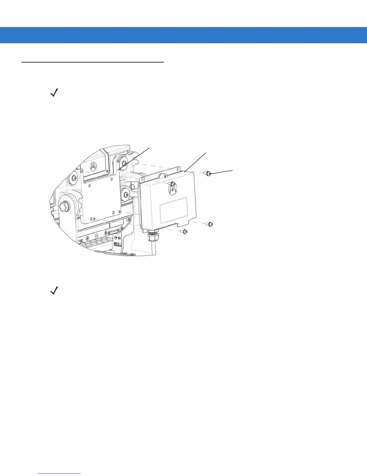
5. Attach the PSU to the back of the vehicle computer.
6. Screw the four M5x14mm screws into the PSU mounting holes and tighten. Torque the screws 20 ± 10%
kgf-cm (17 ± 10% lbs-in).
Figure 2-5
Installing the PSU
NOTE Follow this procedure when using the U-mount. The PSU fastening screws are supplied with the U-mount kit.
PSU
Vehicle Computer
Fastening Screws
NOTE Whenever the PSU needs to be mounted remotely, refer to Installing the PSU on page 2-9 to prepare the
mounting solution. You need to also use an extender cable PN 25-159549-01 to connect the PSU to the
vehicle computer. For power supply and cables, refer to Accessories on page 1-4.

Table of Contents

Other manuals for Motorola VC70N0

Questions and Answers:

Question and Answer IconNeed help?

Do you have a question about the Motorola VC70N0 and is the answer not in the manual?

Motorola VC70N0 Specifications

General IconGeneral
ModelVC70N0
Wireless LAN802.11a/b/g
BluetoothBluetooth v2.1 with EDR
GPSIntegrated GPS
AudioIntegrated microphone and speaker
Expansion SlotSD slot
Operating Temperature-10°C to 50°C (14°F to 122°F)
Storage Temperature-40°F to 158°F / -40°C to 70°C

Related product manuals