6 Mounting
Maschinenfabrik Reinhausen GmbH 2018 335252433/02 EN ECOTAP
®
VPD
®
CONTROL PRO
▪ Separate system parts must be joined by a potential equalization.
▪ The device and its wiring must be at least 10m away from circuit-break-
ers, load disconnectors and busbars.
6.1.2 Wiring requirement of operating site
Note the following when wiring the operating site:
▪ Route the connecting leads in grounded metal cable ducts.
▪ Do not route lines which cause interference (e.g. power lines) and lines
susceptible to interference (e.g. signal lines) in the same cable duct.
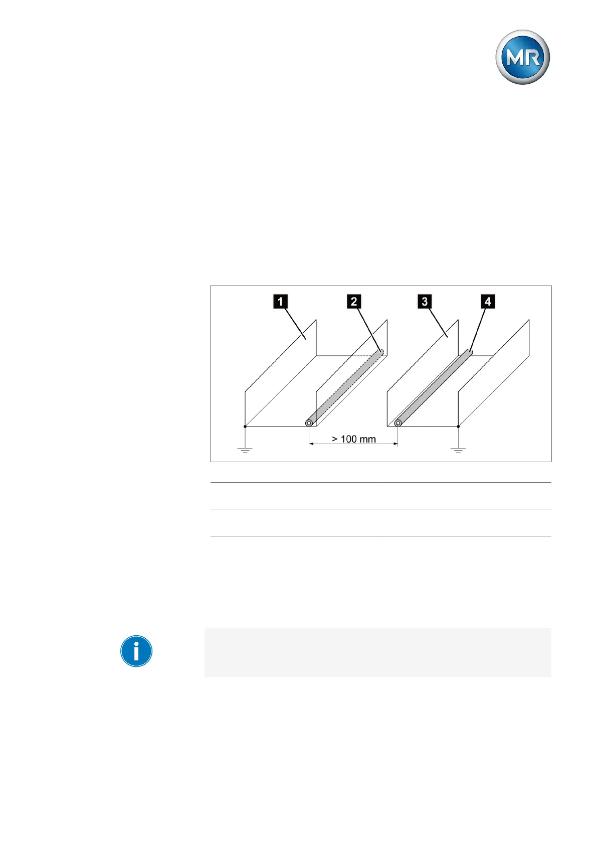
▪ Maintain a distance of more than 100 mm between lines which cause in-
terference and those which are susceptible to interference.
Figure11: Recommended wiring
1 Cable duct for lines causing inter-
ference
3 Cable duct for lines susceptible to
interference
2 Line causing interference (e.g.
power line)
4 Line susceptible to interference
(e.g. signal line)
▪ Short-circuit and ground reserve lines.
▪ Never connect the device with a multi-wire collective pipe.
▪ For signal transmission, use shielded lines with individual conductors (out-
going conductor / return conductor) twisted in pairs.
▪ Connect full surface of shielding (360º) to device or to a nearby grounding
bar.
Using single conductors may limit the effectiveness of the shielding. Con-
nect close-fitting shielding to cover all areas.