6 Mounting
Maschinenfabrik Reinhausen GmbH 201852 5252433/02 ENECOTAP
®
VPD
®
CONTROL PRO
To connect cables to the system periphery, proceed as follows:
ü Use only the specified cables for wiring. Note the cable recommendation.
► Connect the lines to be wired to the device to the system periphery as
shown in the connection diagrams supplied.
6.5.5 Wiring the CPU I assembly
NOTICE
Damage to the device
Assigning the connection cable pins for the COM 2 interface incorrectly can
result in the device being damaged.
► Use the connection cable provided.
► Alternative: Use a connection cable in accordance with the cable recom-
mendation [►Section 6.5.1, Page 50].
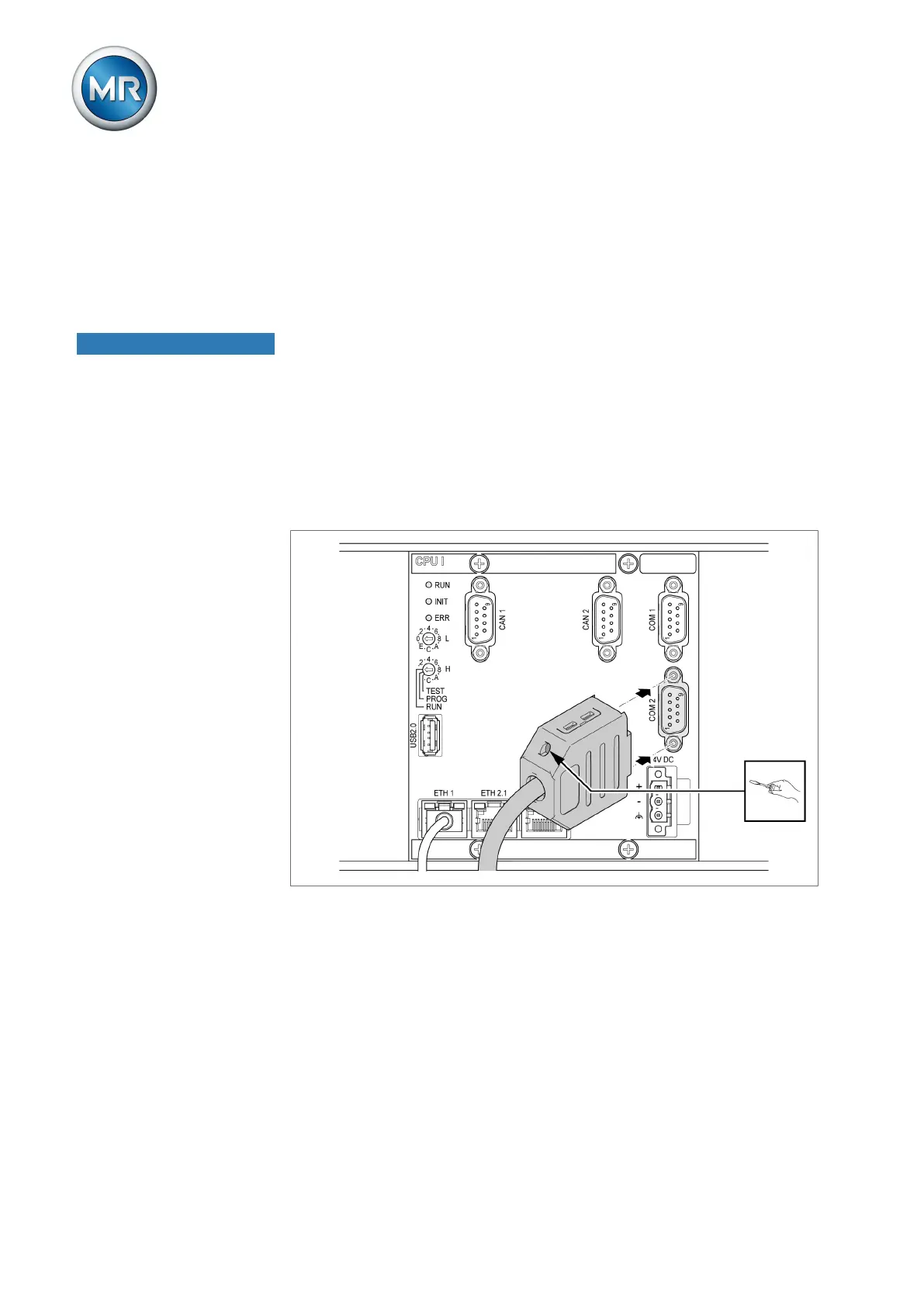
1. Connect the COM 2 interface (D-Sub 9-pole) to the ECOTAP VPD CON-
TROL in accordance with the connection diagram.
Figure37: ECOTAP VPD CONTROL connection via COM 2 interface
 Loading...


