6 Mounting
Maschinenfabrik Reinhausen GmbH 2018 495252433/02 EN ECOTAP
®
VPD
®
CONTROL PRO
6.4.2.3 Mounting the assemblies
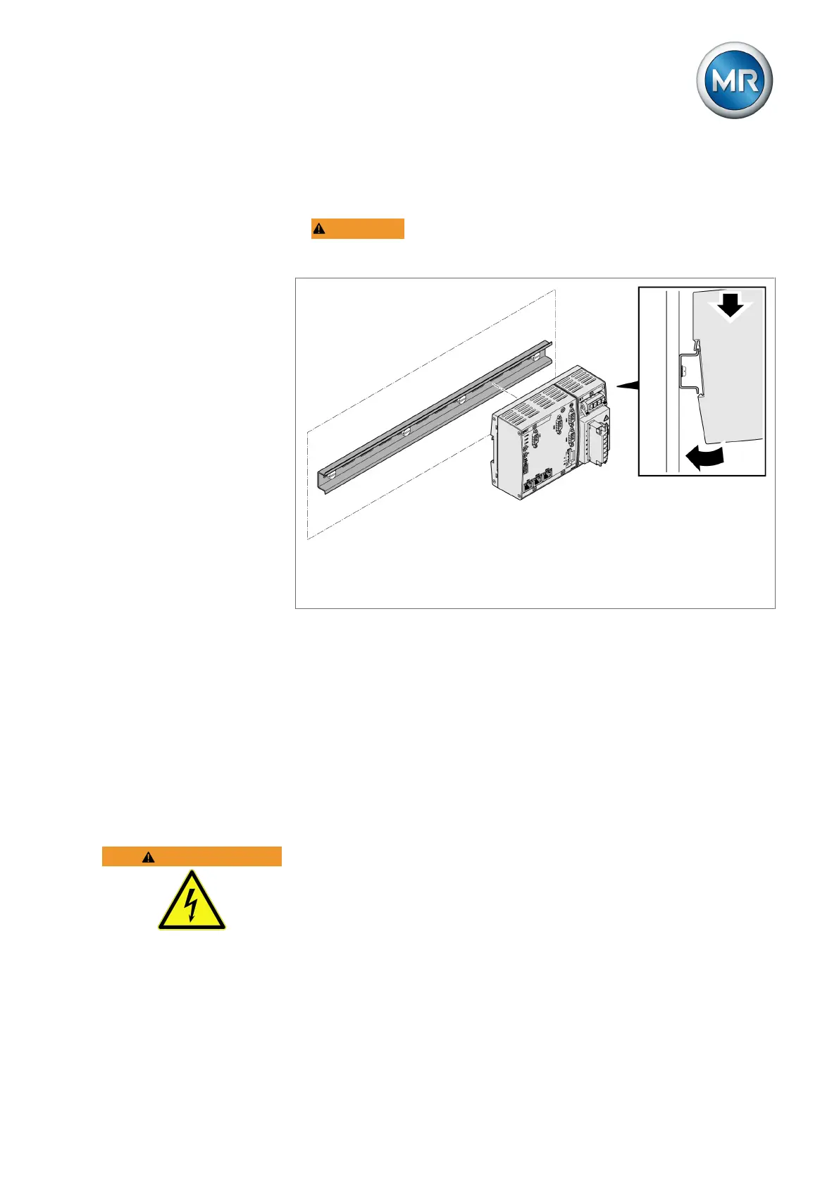
To mount the assemblies on the cap rail, proceed as follows:
1. WARNING! Mount the bus rail with the CPU and UI assemblies on the
cap rail, ensuring that the bus rail engages correctly. Otherwise, it can re-
sult in electric shock due to a faulty connection to the protective ground.
Figure35: Hooking the bus rail into position
2. Optional: Hook the SW3-3 assembly into place on the cap rail.
3. Hook the G1 QS3.241 assembly into place on the cap rail.
4. Hook terminal X5 into place on the cap rail.
5. Hook the voltage divider VD001 into place on the cap rail.
6. Hook terminals X1 and X10 into place on the cap rail.
6.5 Connecting device
The following section describes how to establish the electrical connection to
the device.
WARNING
Electric shock!
Connection errors can lead to death, injury or property damage.
► Ground the device with a protective conductor using the grounding screw
on the housing.
► Note the phase difference of the secondary terminals for the current
transformer and voltage transformer.
► Connect the output relays correctly to the motor-drive unit.