8 Operation
Maschinenfabrik Reinhausen GmbH 201884 5252433/02 ENECOTAP
®
VPD
®
CONTROL PRO
If you use this circuit, set the device as follows:
Parameter Option
Voltage-transformer circuit 3 Ph phase voltage
Current-transformer circuit 3 Ph phase current
Phase angle correction 0°
Table17: Circuit B
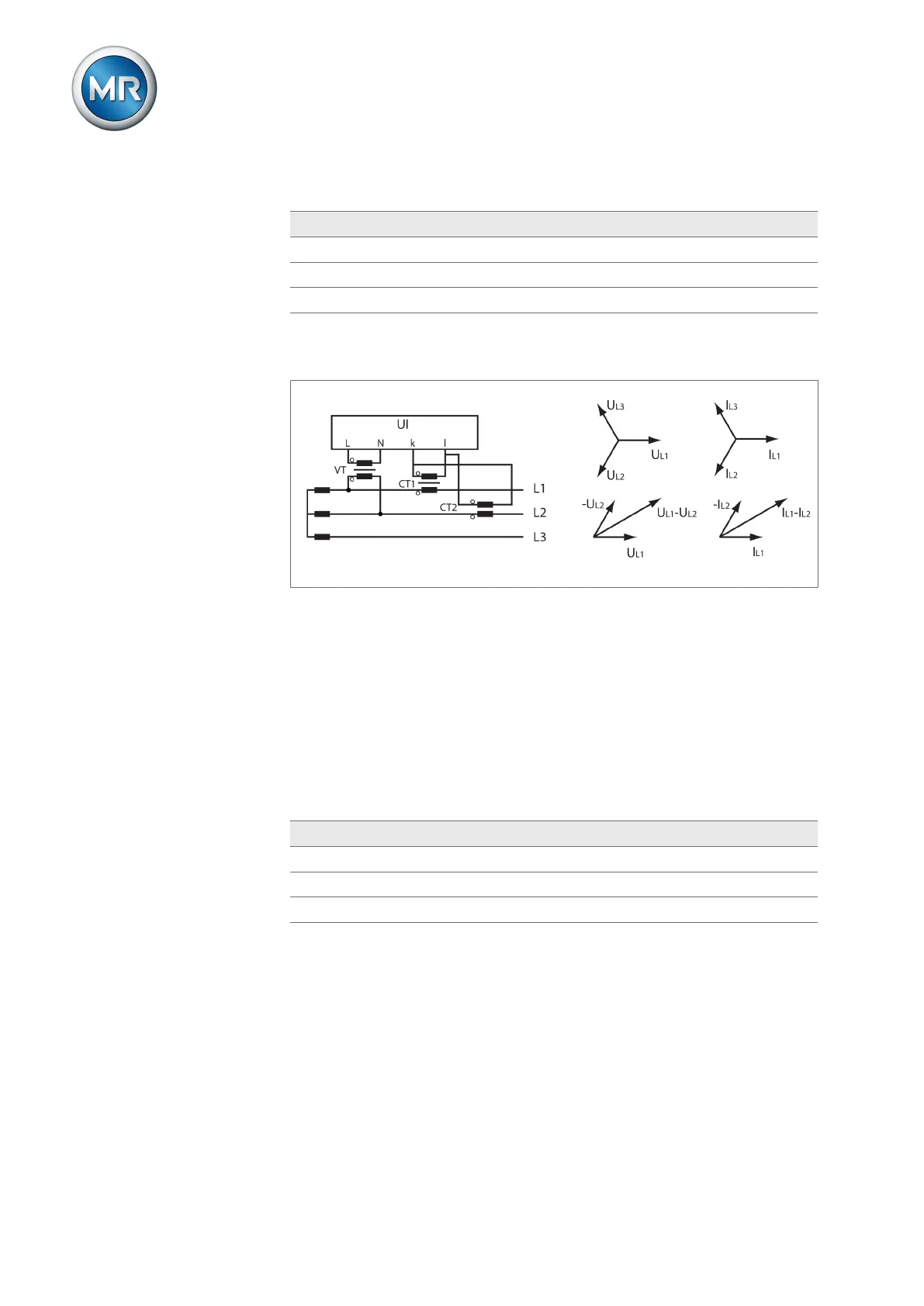
Circuit C
▪ The voltage transformer VT is connected to the phase conductors L1 and
L2.
▪ The current transformer CT1 is looped into the phase conductor L1 and
CT2 into the phase conductor L2.
▪ The current transformers CT1 and CT2 are connected crosswise in paral-
lel (total current = I
L1
+ I
L2
).
▪ The total current I
L1
+ I
L2
and voltage U
L1
-U
L2
are in phase.
▪ The voltage drop on a phase conductor is determined by the current: (I
L1
+
I
L2
) / √3.
If you use this circuit, set the device as follows:
Parameter Option
Voltage-transformer circuit 3 Ph differential voltage
Current-transformer circuit 3 Ph total current
Phase angle correction 0°
Table18: Circuit C