7.22.6 Engine control system – Removal and installation
Preconditions
☑ Engine is stopped and starting disabled.
Special tools, Material, Spare parts
Designation / Use Part No. Qty.
Connector pliers
F30017884 1
Caps for Cannon sockets
Removing engine control sys-
tem from engine
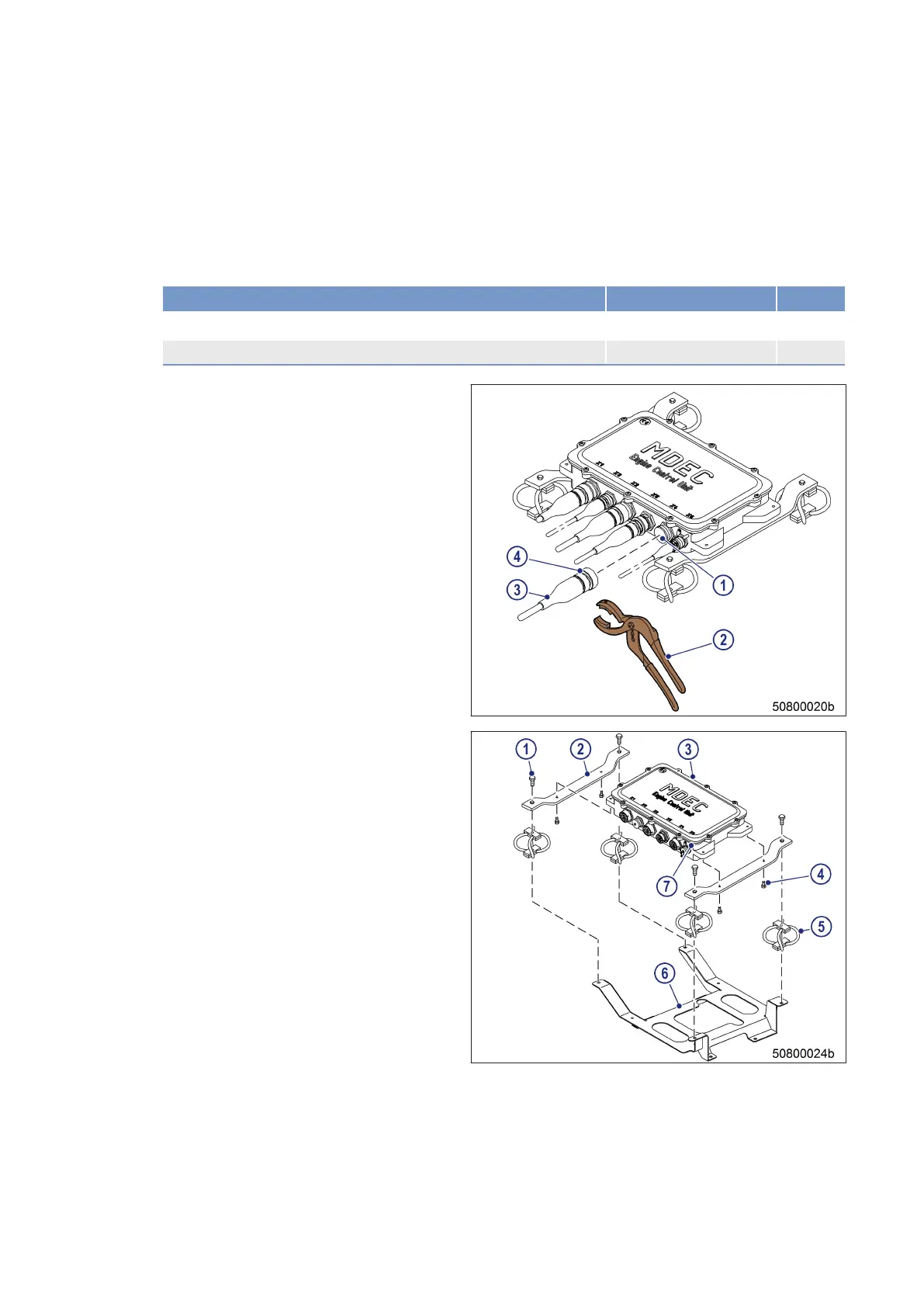
1. Note or mark assignment of cables to con-
nector sockets.
2. Use connector pliers (2) to release the bayo-
net union nuts (4) of the connectors (3) by
turning them counterclockwise.
3. Remove all connectors.
4. Close connector sockets with appropriate
caps (1).
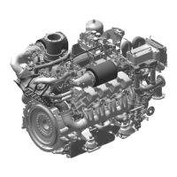
5. Disconnect ground strap from engine control
system grounding stud (7).
6. If the screws (4) are easily accessible:
1. Unscrew screws (4).
2. Remove engine control system hous-
ing (3) from mounting brackets (2).
3. Unscrew mounting brackets (2), cable
shock absorbers (5) and further securing
parts (6) as one unit from engine.
7. If the screws (4) are not easily accessible:
1. Remove screws (1).
2. Remove engine control system hous-
ing (3) together with mounting brack-
ets (2).
3. Unscrew cable shock absorbers (5) and
further securing parts (6) as one unit
from engine.
Installing engine control system on engine
1. Install in reverse order. Ensure correct assignment of plugs and sockets.
2. Use connector pliers to turn the bayonet union nuts of the connectors clockwise until they lock into place.
224 | Accessories for (Electronic) Engine Governor / Control System |
MS150031/06E 2016-010
TIM-ID: 0000008487 - 006