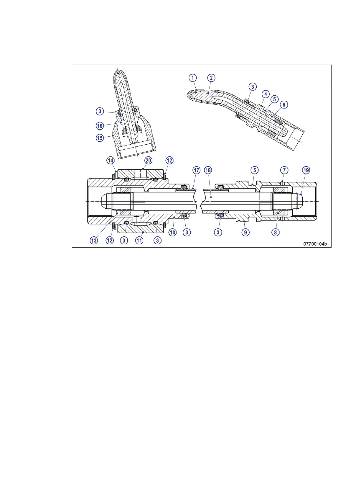
High-pressure unions
1 Jacket pipe
2 HP line
3 O-ring
4 Union nut
5 Recess for O-ring
6 Thrust ring
7 Leakage overflow bore
8 Thrust ring
9 Union nut
10 Union nut
11 Connecting piece
12 Snap ring
13 Thrust ring
14 Compensating disks
15 Union nut
16 Thrust ring
17 External pipe of HP line
18 Internal pipe of HP line
19 Ball-type seal area
20 Leak fuel connection
The HP fuel line is sealed by the thrust ring (8).
In case of leakage around the thrust ring (8) or the HP line (5) fuel escapes into the leakage chamber.
Leak fuel is allowed to escape without pressure via the leakage overflow bore (7). The leakage chamber is
sealed toward the outside by the O-rings (3).
This prevents leaking fuel from escaping.
The union is confirmed as being SOLAS-compliant by DNV and GL.
MS150031/06E 2016-010 | General Information | 25
TIM-ID: 0000002178 - 006