5-Input Connections
12
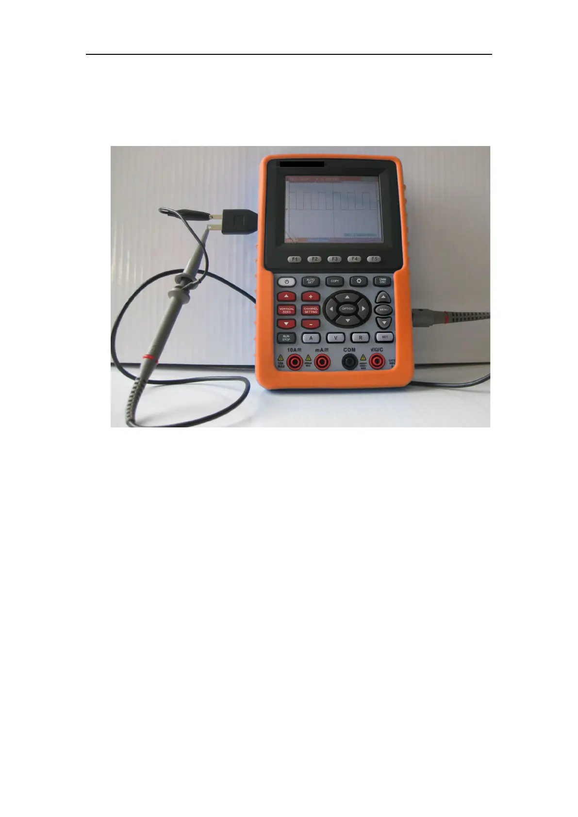
5.1.2 The connection of 1 kHz/5 V Square-wave test signal
At the left side of the oscilloscope, it is a port for testing 1 kHz/5 V square-wave
signal which is used to adjust the probe, shown as Fig.3
Fig.3. The connection of Square-wave test signal
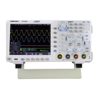
5.2 Front Panel and Keys Overview
See the following Figure 4: