8-Advanced Function of Oscilloscope
The following Table describes the Vertical Channel menu:
Function menu Setting Description
Coupling
DC
The dc component in the input signal is blocked.
The ac and dc components of the input signal are allowed.
Input signal is interrupted.
Channel
OFF
ON
Close the channel.
Open the channel.
Probe
1 X
10 X
100 X
1000 X
Select one according to the probe attenuation level to ensure a
correct vertical scale reading.
Inverted
ON
Waveform is displayed normally.
Open the Invert function of the waveform setting.
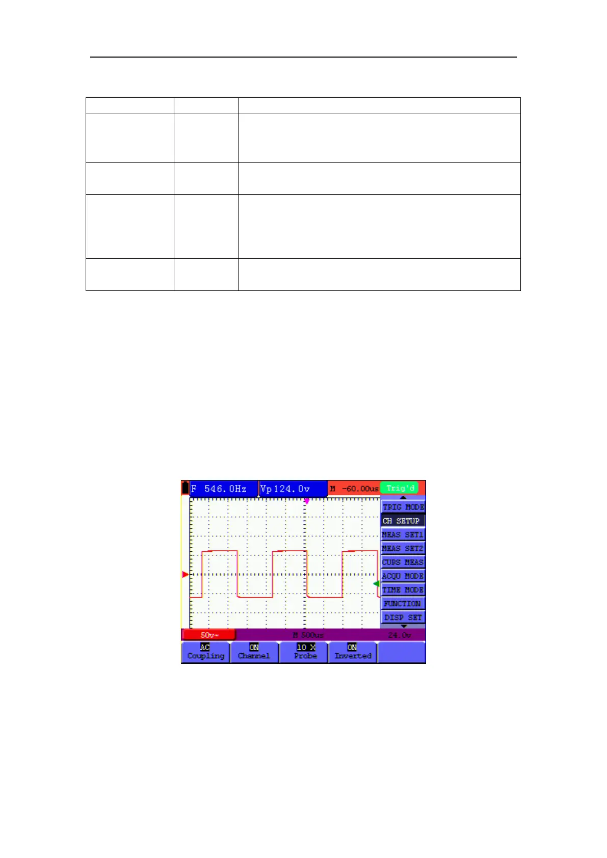
8.2.1 Setting the Channel Coupling
Press F1 key, set Coupling as AC to make an AC coupling setting. The DC component contained
in the tested signal is blocked.
Press F1 key, set Coupling as DC to make a DC coupling setting. Both DC and AC components
contained in the tested signal are permitted.
Press F1 key, set Coupling as Ground to make a Ground coupling setting. Input signal is
interrupted.
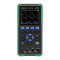
The waveform is displayed as the following figure 32, figure 33, and figure 34.
Figure 32: AC Coupling