W415-2912 / E / 06.02.21
EN
22
venting requirements
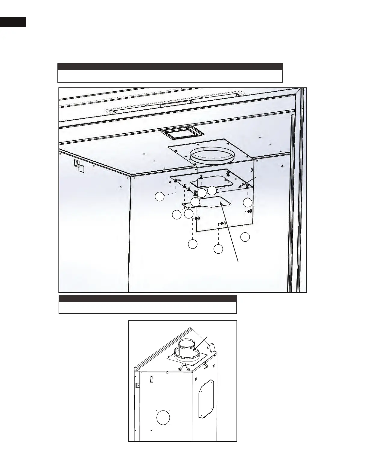
Fig. 3
Do not overtighten. The gasket needs only to be snug against the fi rebox.
note:
E. Place the gasket (supplied) over the 5” (127mm) fl ue collar assembly and bend along perforation.
F. From inside the fi rebox, install the 5” (127mm) exhaust collar with gasket and the exhaust outlet reducer
plate up through the top of the fi rebox, and secure with the the 10 hex head 3/4" black screws supplied in
the manual baggie (Fig. 2).
G. Reinstall the log set, glass
door, and safety barrier.
Fig. 2
EXHAUST
FLUE COLLAR
F
F
F
F
F
F
F
G
G
F
RESTRICTOR
PLATE
(IF REQUIRED)
EXHAUST
OUTLET
REDUCER
Restrictor plate installation (see “restricting vertical vents” section).
note:

 Loading...