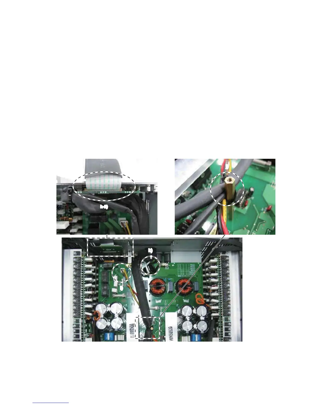
At the stage as shown in Fig. 26, connect the
following wires.
CN313: WK68760
CN201: WK68770
CN202: WK14200 from OUTANH board
CN203: WK66350 from PSANHB board
h-2) After connecting the wire (WM15830) to it, install
the RS232-GPI circuit board to the enclosure.
i) Twist the wires (yellow, brown) of the power switch
assembly more than three times, and connect it to the
connector (CN103) of the PSANHA circuit board.
j) Fasten these wires (WK17900, WK17910, WK94690 and
WK02090) with a cord holder to the hexagonal spacer.
k) Connect the wire of the AC-INLET according to the step
“5. Wiring of the AC-INLET”.
Note: Do not fasten the GND wire with a cord holder.
図 26 の段階で下記の線材を接続しておきます。
CN313:WK68760
CN201:WK68770
CN202:WK14200OUTANHシートから
CN203:WK66350PSANHBシートから
h-2)RS232-GPI シートに線材(WM15830)を接続し
た後、RS232-GPI シートを筐体へ取り付けます。
i) 電源 SW の線材(黄色、茶色)を 3 回以上捻った後、
PSANHA シートのコネクター(CN103)へ接続します。
j) 線材(WK17900、WK17910、WK94690、WK02090)
をインシュロックタイで六角スペーサーへ固定します。
k) 「5. AC インレットの配線」にしたがって AC インレッ
トの線材を接続します。
注意: GND 線材はインシュロックタイで固定しない
でください。
Fig. 26
(図 26)
h-2)
j)
k)
i)
NXAMP4x4
17
 Loading...