l)
m-1)
m-2)
m-3)
m-1)
m-2)
m-3)
l)
n)
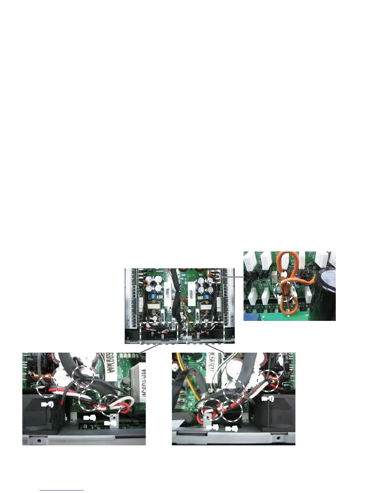
l) Connect the wire (WK14210) of PA unit (CH1) to the
connect
or (CN312) of the PSANHA circuit board.
(Draw a black tube to the PA unit side.)
Connect the wire (WK14210) of PA unit (CH2) to the
connector (CN315) of the PSANHA circuit board.
(Draw a black tube to the PA unit side.)
Fasten the wire (WK14210) and the wire of FAN with a
cord holder as shown in the figure. (Fig. 24)
m) Twist the wires (white, red, black) of the PA unit more
than two times, and connect them to the FASTON
terminals according to the wire color displayed on the
PSANHA circuit board.
m-1, 2) Fasten these wires (white, red, black) together
with wires (WM04880, WK16820) with a cord
holder as shown in the figure.
m-3) Bend these wires (white, red, black) and fasten
them with a cord holder as shown in the figure.
n) Fasten the wire (WN52520) with a cord holder.
(Fig. 25, 26)
Note: When connecting the connector assembly to
the CONTROL circuit board
、
confirm that the
connector housing pin number of the connector
assembly is the same as the connector pin
number of the circuit board.
l) PA ユニット(CH1)の線材(WK14210)を PSANHA シー
トのコネクター(CN312)へ接続します。(スミチュー
ブを PA-UNIT 側に寄せます。)
PA ユニット(CH2)の線材(WK14210)を PSANHA シー
トのコネクター(CN315)へ接続します。(スミチュー
ブを PA-UNIT 側に寄せます。)
線材(WK14210)と FAN の線材をインシュロックタ
イで図のように固定します。
m) PA ユニットの線材(白、赤、黒)を 2 回以上捻った
後、PSANHA シートに表示された線材の色にしたがっ
てファストン端子に接続します。
m-1、2)これらの線材(白、赤、黒)を線材(WM04880)、
(WK16820)と一緒にインシュロックタイで
固定します。
m-3) それら(白、赤、黒)の線材を折り曲げた後、
インシュロックタイで固定します。
n) 線材(WN52520)を図のようにインシュロックタイで
固定します。
注意: CONTROL シートに束線を接続するとき、
線材側のコネクターハウジングのピン数が
CONTROL シート側のコネクターのピン数と
同じであることを確認してください。
Fig. 27
(図 27)
NXAMP4x4
18
 Loading...