100 - FORM NO. 56043124 - Condor XL
APPENDIX
LT GREEN/PURPLE 18
LT GREEN/BLACK 18
BLUE/WHITE 18
BLUE/PINK 18
LT GREEN/RED 18
BLACK/LT GREEN 18
DK BLUE/ORANGE 18
PURPLE/YELLOW 18
UNUSED
GREEN/YELLOW 18
LT BLUE/PINK 16
DK BLUE 18
PINK/YELLOW 16
BLACK/RED 16
PURPLE 16
PINK 18
S 5V EXT 2 (FPP2 ONLY)
R5VRTN2
PCAN1-
NCAN1+
M5VEXT1
L5VRTN1
K FPP1
J FPP2/IVS
H FUEL SELECT (AUX DIG 1)
GMIL
FSTARTCOMMAND
EAUXPWM2
D FUEL PUMP +
C FUEL PUMP -
BALTEXCITE
A VSW
PINK/DK GREEN 16
TAN/DK GREEN 18
RED/BLACK 18
RED/WHITE 18
TAN/BLACK 18
TAN/RED 18
GRAY/DK BLUE 18
GRAY/ORANGE 18
DK BLUE/YELLOW 18
YELLOW/DK BLUE 18
TAN 18
BLACK 16
GRAY 18
BROWN/WHITE 16
WHITE/BROWN 16
S12VRELAYEDPOWER
RAUXANAPD1
PVS-
NVS+
MAUXDIG3
LAUXDIG2
K GOV SELECT 1
J GOV SELECT 2
HAUXANAPU1
GAUXANAPU2
FAUXPWM1
E GROUND
DTACH
CAUXPWM5
B AUX PWM 5 RECIRC
A UNUSED
ECM Detail
CONNECTOR 1
CONNECTOR 2
BLACK/LT GREEN 18
LT GREEN/RED 18
DK GREEN 18
ORANGE 18
BLUE/PINK 18
BLUE/WHITE 18
1ANARTN
25VREF
3PCTX
4PCRX
5 UNUSED
6 UNUSED
7CAN1+
8CAN1-
GASOLINE SENSOR INTERFACE
GRN/YEL 18-1
BLU/PINK 16-1
PINK/YEL 16-1
BLK/RED 16-1
PINK 16-7
PINK 16-4
S
R
CAN1 (-) P
CAN1 (+) N
M
L
K
J
H
MIL OUTPUT G
START COMMAND F
E
FUEL PUMP (+) D
FUEL PUMP (-) C
ALT. EXCITE B
IGN. SWITCH INPUT A
X1
GRA/BLU J2-30
GRA/ORN J2-29
VIO/BLU J1-30
GRA J1-1
S
R
P
N
M
L
K
J
H
G
COOLANT TEMP. OUTPUT F
E
D
RUN SIGNAL (GROUND) C
B
A
X2
WHT/GRN 18-1
GRN/RED 18-1
GRN/WHT 18-1
BLK/GRN 18-1
D
C
B
A
X78
(GASOLINE
MODELS ONLY)
DIAGNOSTIC CONNECTOR
Machine
Harness Connectors
ECM
Harness Connectors
WHITE/LT GREEN 18
LT GREEN/RED 18
LT GREEN/WHITE 18
BLACK/LT GREEN 18
D
C
B
A
Wiring
Harness Wiring Harness Component Description
Item
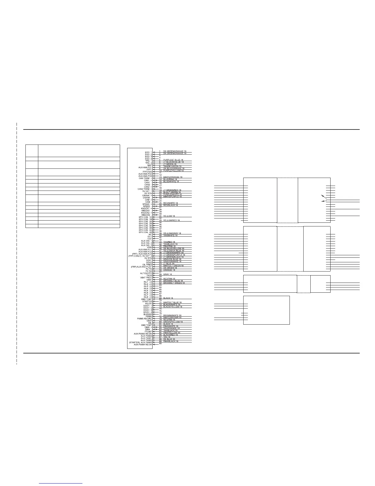
A ECM Wiring Connector (90 Pins)
B Gasoline/Petrol Fuel Sensor Interface Connector (fuel pressure
regulation and temperature sensor manifold assembly)
C Engine Diagnostic Communication Port (8 Pin)
(MIL shorting location)
D Ignition Coil Pack Wiring Connector
E Engine Oil Pressure Switch
F Crankshaft Position Sensor Connector
G Throttle Fly Actuator Motor Connector (Bosch)
H EGO #1 Sensor Wiring Connector
I Combined TMAP Engine Air Temperature and MAP Sensor Wiring
Connector
J Engine Coolant Temperature (ECT) Sensor Connector
K Engine Starter Solenoid Wire Connector
L EGO #2 Sensor Wiring Connector
M LPG Fuel Lockoff Wiring Connector
N LPG Temp Sensor Wiring Connector
P EPR Connector (LPG) Fuel Regulator
Q Gasoline Fuel Injectors
Definition of Terms for Computerized Engine Controllers
•ANA-RTN:
• ECM: Engine Control Module
• EGO: Exhaust Gas Oxygen Sensor (O2)
• EPR: Electronic Pressure Regulator
• IAT: Intake Manifold Air Temperature
• MAP: Intake Manifold Absolute Pressure
• MIL: Malfunction Indicator Light
• VSW: Switched Battery Voltage
• VBAT: Battery Voltage
THROTTLE INPUT
(12V FOR 2400 RPM)
THROTTLE INPUT
(12V FOR 2200 RPM)
 Loading...


