46 - FORM NO. 56043124 - Condor XL
™
ADJUSTMENTS/REPAIRS
SIDE BRUSH TILT ADJUSTMENT
1 See Figure 10. Disconnect one of the two Rod Ends from its mounting tab.
2 Loosen the Jam Nut.
3 Rotate either Rod End to lengthen or shorten the Rod/Rod End assembly as neces-
sary to get the correct brush angle to the fl oor.
Note: The nominal factory dimension between the Rod End stud centers is 7.5”
±.06” (190.5 mm ±1.5 mm).
4 Make sure the threaded stud on the Rod End will align with the matching hole in the
mounting tab, then tighten the Jam Nut.
5 Reinstall the Rod End into the mounting tab.
6 Run the brush up and down to check for correct brush angle with the fl oor.
7 Repeat steps 1 through 5 above as necessary.
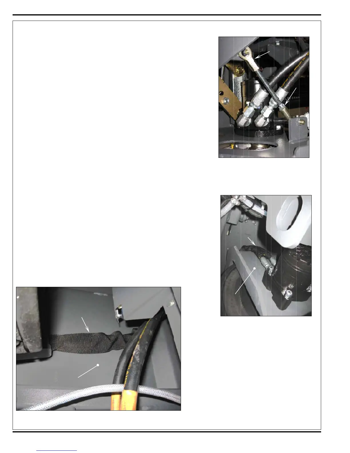
TRACTION DRIVE MOTOR HOSE ROUTING
If the traction drive motor or the Hydraulic Hoses to the motor are replaced or repaired, it’s
important to route the Hoses correctly when reinstalled to prevent wear or damage to the
Hoses and surrounding components.
When reinstalling the traction drive motor Hydraulic Hoses:
1 Tighten the hoses at the bulkhead fi ttings on the frame.
2 Turn the steering wheel all the way toward the left.
3 Make sure the Hoses are routed up and inside the channel in the Drive Wheel Weld-
ment as shown in Figure 11, and fl at against the bottom of the Frame as shown in
Figure 12 below.
4 Twist the Hoses as necessary so they lie fl at against the top of the Frame as shown in
Figure 12, then tighten the fi ttings at the traction drive motor.
5 Turn the steering wheel all the way toward the left and right several times to make sure
the Hoses are not rubbing against the surrounding components.
FIGURE 10
FIGURE 11
FIGURE 12
Rod End (2)
Jam
Nut
Hydraulic
Hoses
Drive Wheel
Weldment
Hydraulic
Hoses
Bottom of
Frame
 Loading...


