NTI ENTERPRISE ENVIRONMENT MONITORING SYSTEM
28
The initial page includes the Summary page, and a menu to the left with access to all pages used to manage the functions of the
ENVIROMUX.
Function Description
MONITORING Monitor all the sensor and data input received by the ENVIROMUX (below)
ADMINISTRATION Configure all network and multi-user access settings (page 54)
SMART ALERTS View and configure the Events used for Smart Alerts and the Smart Alerts
themselves (page 81)
LOG View and configure the Event and Data Logs (page 93)
SUPPORT Links for downloading a manual, the MIB file, or firmware upgrades
LOGOUT Log the user out of the ENVIROMUX web interface
Monitoring
Under Monitoring, there are links to view the sensors, IP cameras, IP address data and more being monitored by ENVIROMUX.
Topic Description
Summary Lists all monitored items , including their type, description, value, and status
Sensors Provides a link to view the status of specific Internal and External Sensors (page 31 and 36 )
Digital Inputs Provides a link to view the status of each Digital Input (page 44)
IP Devices Provides a link to view the status of only the IP Devices and a link to add them (page 49 )
Output Relays Provides a link to view the status of each Output Relay (page 47)
IP Cameras Provides a link to view each IP camera defined- with a link to the configuration page (page 49)
Power Supplies Provides a link to view the status of each power supply- with a link to the configuration page (page 29)
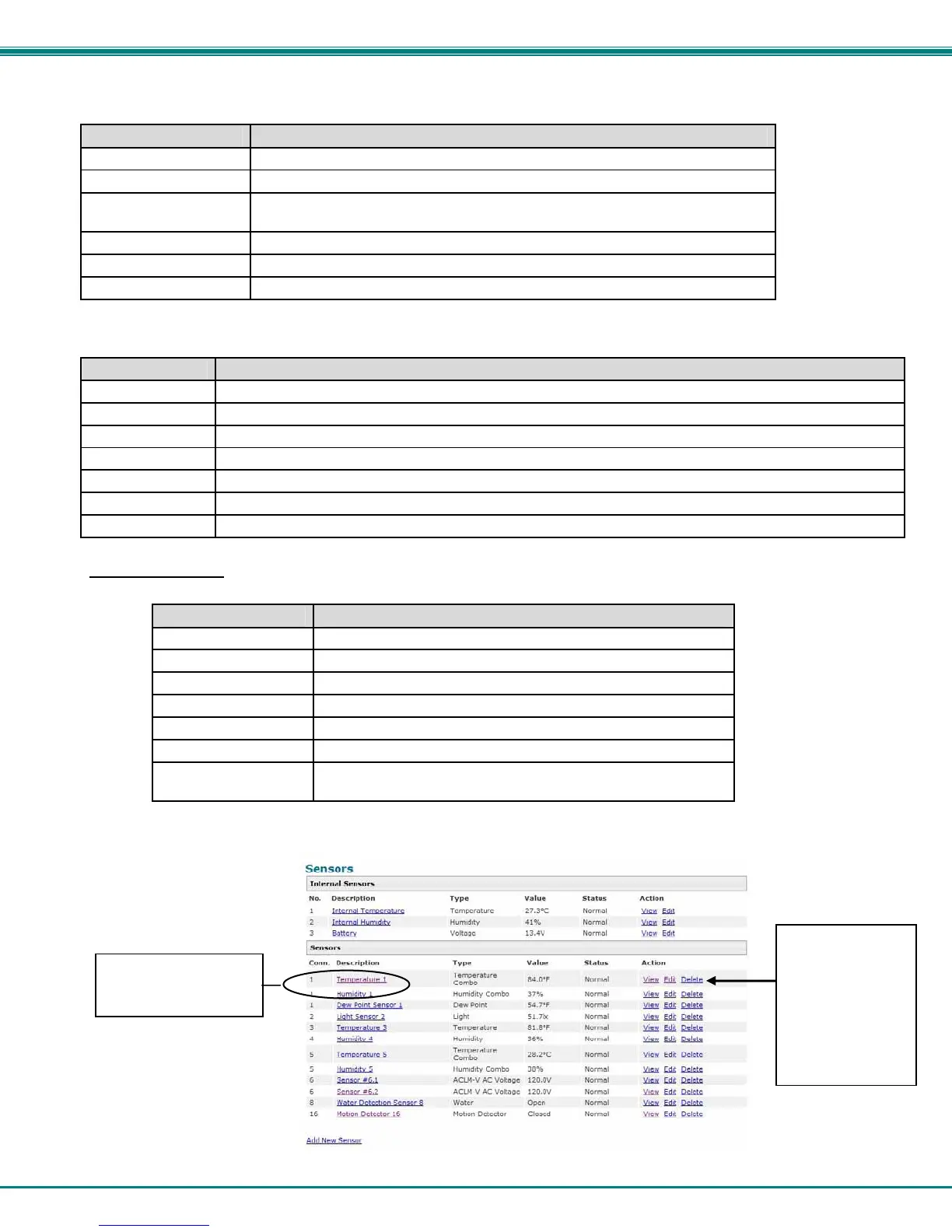
Summary Page
The Summary Page displays the data for all 6 categories of monitored items:
Category Description
Internal Sensors there are three inside the ENVIROMUX
Sensors sensors that connect to the RJ45 connectors
Digital Inputs sensors that connect to the terminals "Digital In"
IP Devices IP Addresses that can be monitored by ENVIROMUX
Output Relays Relays that open or close depending on alert status
AC Power Indicates the status of the power supply(s)
Smart Alerts
Displays the status of each Smart Alert configuration (page 81)
and provides link to respond when triggered
To see the settings of each sensor, click on the link in the description column for the desired sensor. Click on the browser's Back
button to return to the summary.
Figure 28- Summary Page
Double-function
sensor (see page 25)
o delete a sensor
from this list,
select “Delete”.
A pop-up
confirmation
window will
appear before
removal takes
place.
 Loading...