CHAPTER 11
ENTRY GUIDE ASSEMBLY
37
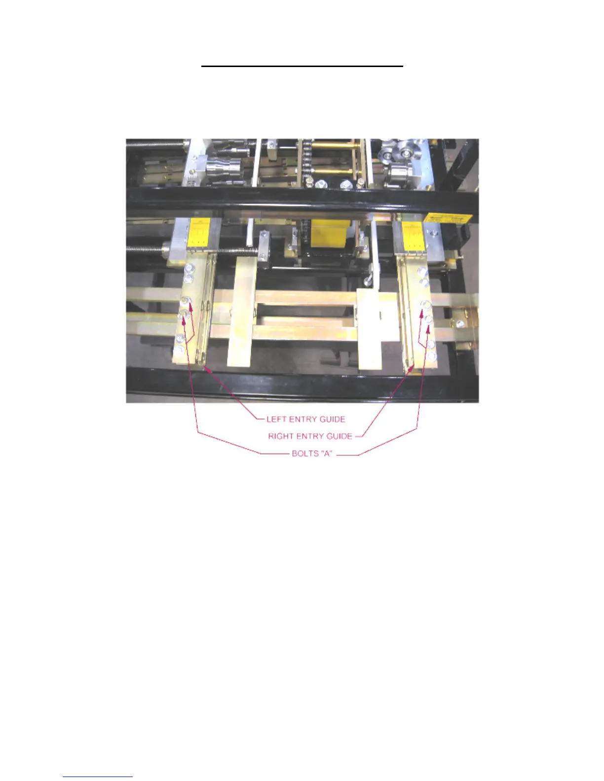
7. Slide the Left Entry Guide to the left or right to accept the new coil width. Make
sure that the coil is captured snugly between the entry guides and re-tighten the
two “A” bolts.
Figure 23: Entry Guide Assembly
LEFT TOOLING RAIL TO ENTRY GUIDE ALIGNMENT
(Figure 24 to Figure 27)
The Tooling Rail Adjustment Handle is used to move the Left Tooling Rails assemblies
to the left or right to align them to the Left Tooling Rail Marker Plate whenever a
width change or tooling change has been made.
1. Using the Tooling Rail Adjustment Handle (Figure 24) align the notch on the
tooling rail marker plate to the alignment pin located in the Left Entry Guide.
Make sure to choose the notch that corresponds to the desired leg configuration as
noted on the decal on the marker plate (Figure 25). The Tooling Rail Adjustment
Handle is spring loaded to allow it to disengage from the width adjustment gear
(Figure 26). Press the handle inward (Figure 27) to engage the width adjustment
gear and turn the handle clockwise to move the tooling outward or counter-
clockwise to move it inward.