CHAPTER 14
WIDTH CHANGE PROCEDURE
47
22. Visually site through the male entry die and rough align it to the forming tool
“line of fire” by sliding it left or right. Re-install the two “C” bolts into holes
that correspond to the slots. Do not tighten the bolts at this time, just snug
them up.
23. Install the male exit die in the same manner aligning it to the entry die and
again, just snug the bolts.
24. Start the machine and carefully jog the panel up to the shear. Check to see if
the panel will pass through the entry shear die. If not FIRST SHUT THE
MACHINE OFF, then move the entry die so that the panel will pass through
it.
Adjust the entry die so that it is as close to the outside vertical portion of the leg
as possible without touching it. Once this is done, tighten the two “C” bolts on the
entry male shear die assembly.
25. Check the exit shear die to ensure that the material will pass through it. If not
adjust as necessary.
26. Start the machine again and slowly jog the panel approximately 6” past the
exit male shear die assembly and stop. Again, TURN THE MACHINE OFF.
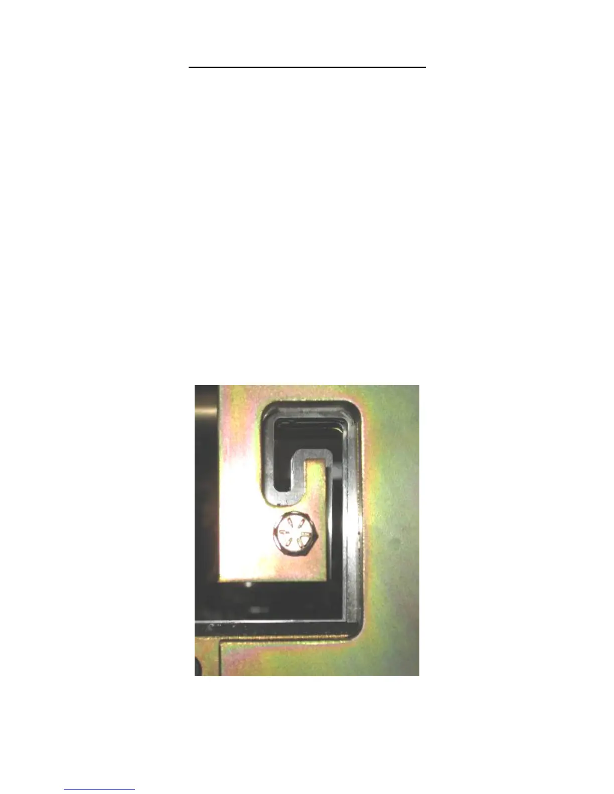
27. Adjust the exit male shear die assembly so that it is offset to the outside of the
entry die by approximately 1/64” and lock down the two “C” bolts (Figure 36)
This offset is necessary so that after a cut is made, the leading edge of the
panel does not hang up on the exit die.
Figure 36: Exit Die Adjustment
28. Look down the leg of the panel and make sure that the entry and exit male
shear die assemblies are not touching the panel as it passes through them.