CHAPTER 15
PROFILE CHANGEOVER PROCEDURE
54
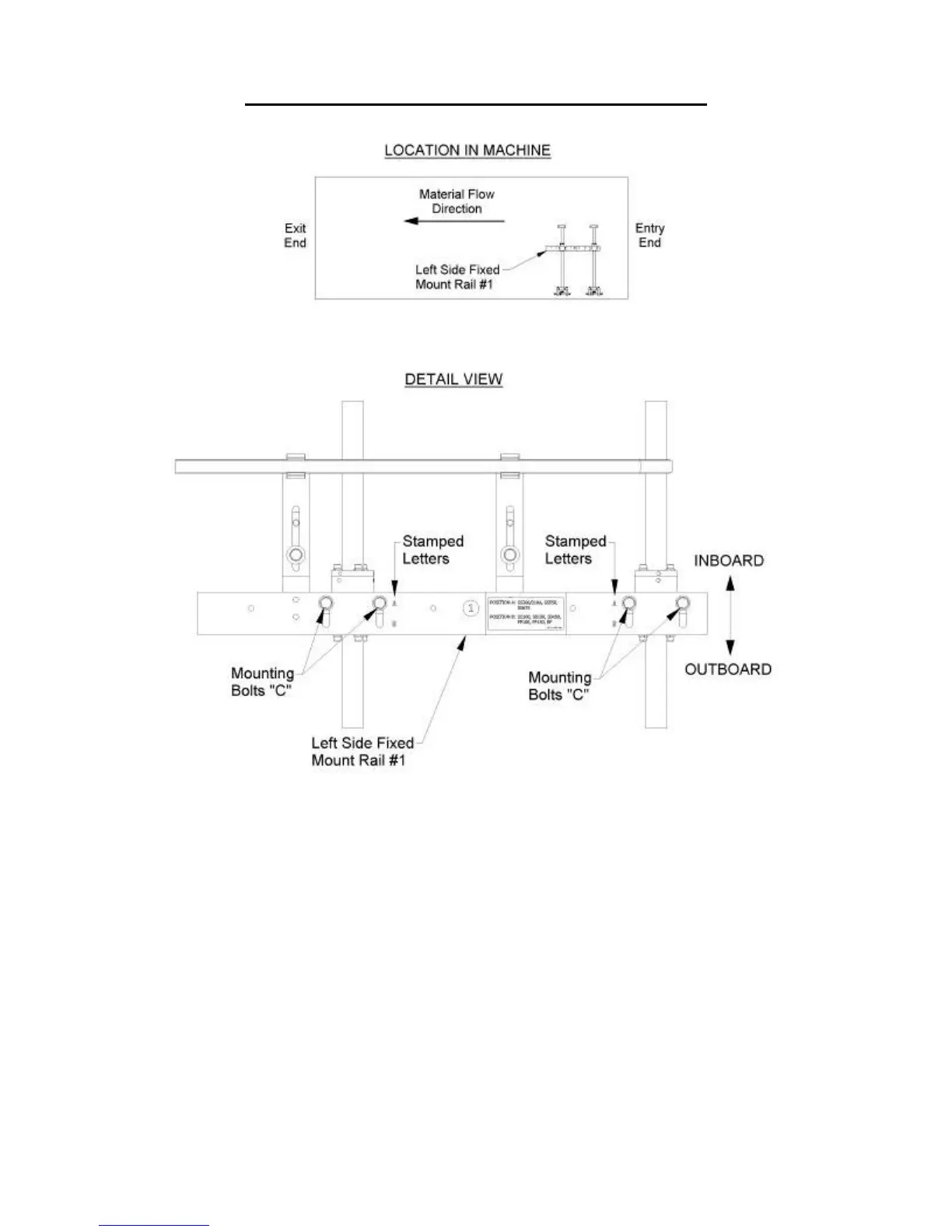
Figure 45: Left Side Fixed Mount Rail
Figure 46: Shown in the “A” position
7. Find the R1 Tooling Rail and set it flat on top of the Right Side Fixed Mount Rail
#1 making sure the correct number shows in Sight Hole “C” (Figure 47). Thread
the two mounting bolts into the slots of the rail and finger-tighten them. Pull the
Tooling Rail assembly toward the outside of the machine until the two Tooling
Rail Spacers “D” contact the face of the Fixed Mount Rail. Hold it in place while
tightening the mounting bolts with a ½” wrench.