CHAPTER 15
PROFILE CHANGEOVER PROCEDURE
60
19. Loosen the Slide Lock Bolts “D” on the top and bottom bead assemblies
(Figure 21) and slide each bottom and top roll assembly left or right to center
them on the 4” and 8” marks on the panel.
20. Lock the two top bead assemblies in the correct position by tightening the “D”
bolt on each assembly (Figure 21). Next align the bottom bead rollers to the tops
so that the ends of the top and bottom rollers are flush with each other and tighten
the bottom “D” bolts on these 2 assemblies.
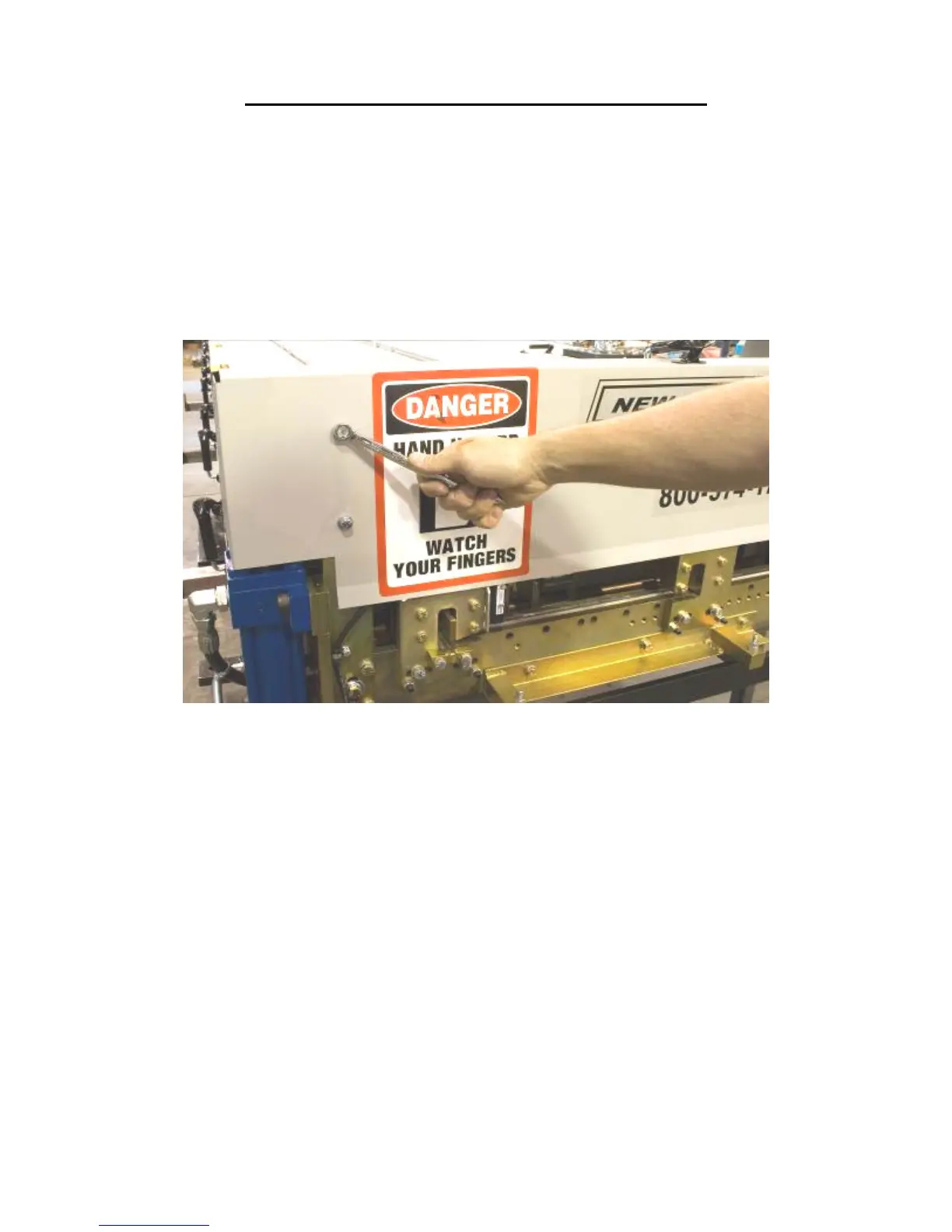
21. Using a 7/16” wrench, remove the Shear Cover and set aside.
Figure 56: Removing Shear Cover
22. Remove the two “C” bolts on the exit male and female shear die assemblies
located in the slotted holes at the bottom edge of the die holder (Figure 57). Store
the shear dies with the profile you just removed, and set the bolts aside for use
when installing the new shear dies.