CHAPTER 15
PROFILE CHANGEOVER PROCEDURE
55
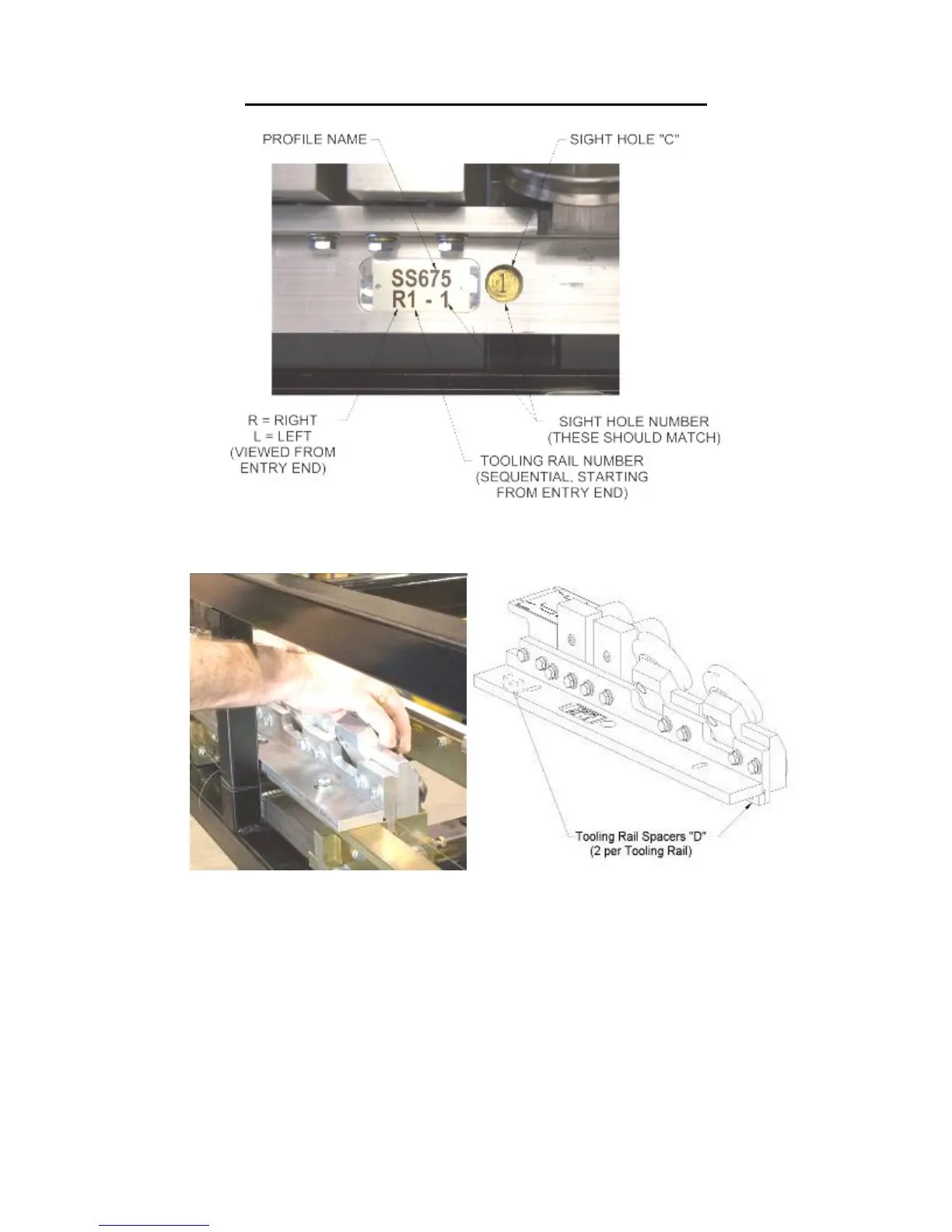
Figure 47: Tooling Rail Identification
Figure 48: R1 Tooling Rail Spacers
8. Continue installing the remainder of the right and left tooling rails in sequence as
described above.
Special Instructions for the SS100, SS150, SS450, and BP Profiles:
The Left #1 Tooling Rail Assembly (L1-1) for these profiles can be mounted
in one of two possible positions based on the required height of the male leg.
When mounting this Tooling Rail Assembly for use with the SS150 or BP
1½" profiles pull it toward the outside of the machine until the two Tooling
Rail Spacers “D” contact the face of the Left Side Fixed Mount Rail #1