LPC5411x All information provided in this document is subject to legal disclaimers. © NXP Semiconductors N.V. 2018. All rights reserved.
Product data sheet Rev. 2.1 — 9 May 2018 55 of 105
NXP Semiconductors
LPC5411x
32-bit ARM Cortex-M4/M0+ microcontroller
[1] The supply current per peripheral is measured as the difference in supply current between the peripheral
block enabled and the peripheral block disabled using PDRUNCFG0/1 registers. All other blocks are
disabled and no code accessing the peripheral is executed.
[2] The supply currents are shown for system clock frequencies of 12 MHz, 48 MHz, and 96 MHz.
[3] Typical ratings are not guaranteed. Characterized through bench measurements using typical samples.
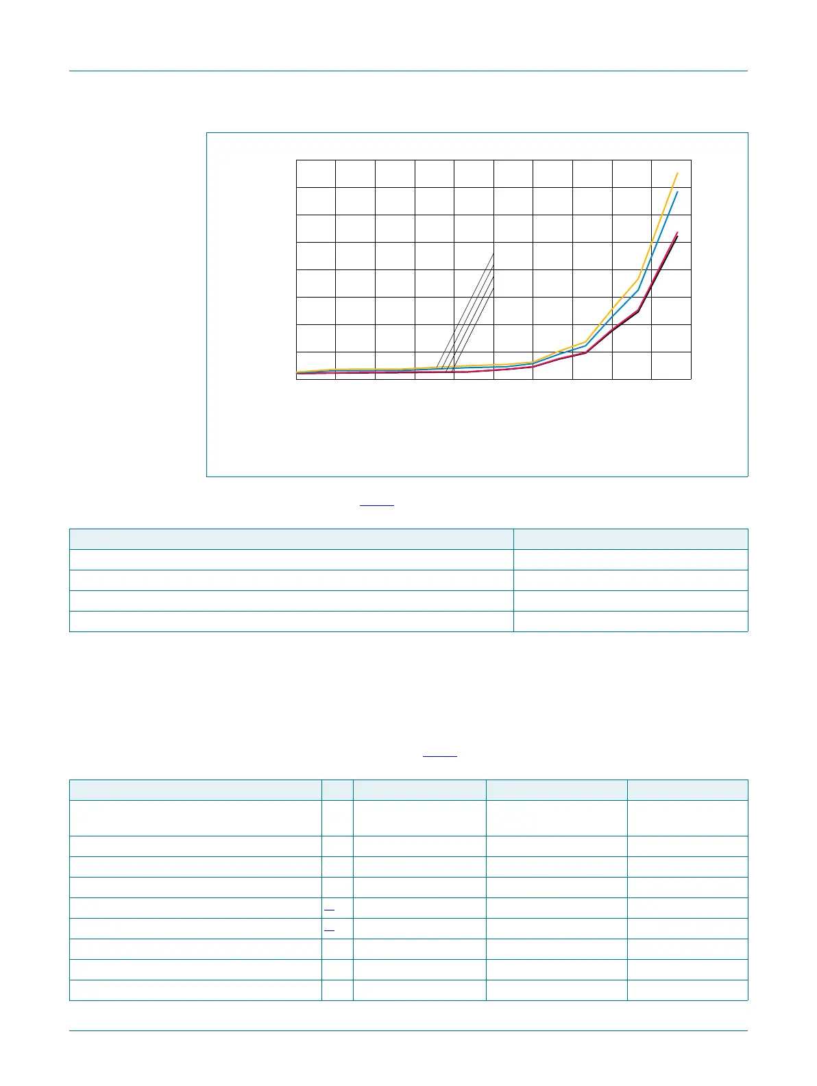
Conditions: RTC disabled (RTC oscillator input grounded)
Fig 12. Deep power-down mode: Typical supply current I
DD
versus temperature for
different supply voltages V
DD
DDD
7HPSHUDWXUH&
,
''''
,
''
$$$
999
999
999
999
Table 18. Typical peripheral power consumption
[1][2][3]
V
DD
= 3.3 V; T
amb
= 25 °C
Peripheral I
DD
in uA
FRO (12 MHz, 48 MHz, 96 MHz) 100.0
WDT OSC 2.0
Flash 200.0
BOD 2.0
Table 19. Typical AHB/APB peripheral power consumption
[3][4][5]
T
amb
= 25 °C, V
DD
= 3.3 V;
Peripheral I
DD
in uA/MHz I
DD
in uA/MHz I
DD
in uA/MHz
AHB peripheral CPU: 12 MHz, sync
APB bus: 12 MHz
CPU: 48 MHz, sync
APB bus: 48 MHz
CPU: 96MHz, sync
APB bus: 96 MHz
USB 2.09 2.09 2.09
Temperature sensor 0.02 0.01 0.01
DMIC 0.17 0.17 0.17
GPIO0
[1]
0.65 0.65 0.65
GPIO1
[1]
0.56 0.56 0.56
DMA 0.34 0.43 0.43
CRC 0.50 0.54 0.54
MAILBOX 0.12 0.12 0.12

 Loading...


