MPC5777M Microcontroller Data Sheet, Rev. 6
Electrical characteristics
NXP Semiconductors46
NOTE
PORST can optionally be connected to an external power-on supply circuitry.
NOTE
No restrictions exist on reset signal slew rate apart from absolute maximum rating
compliance.
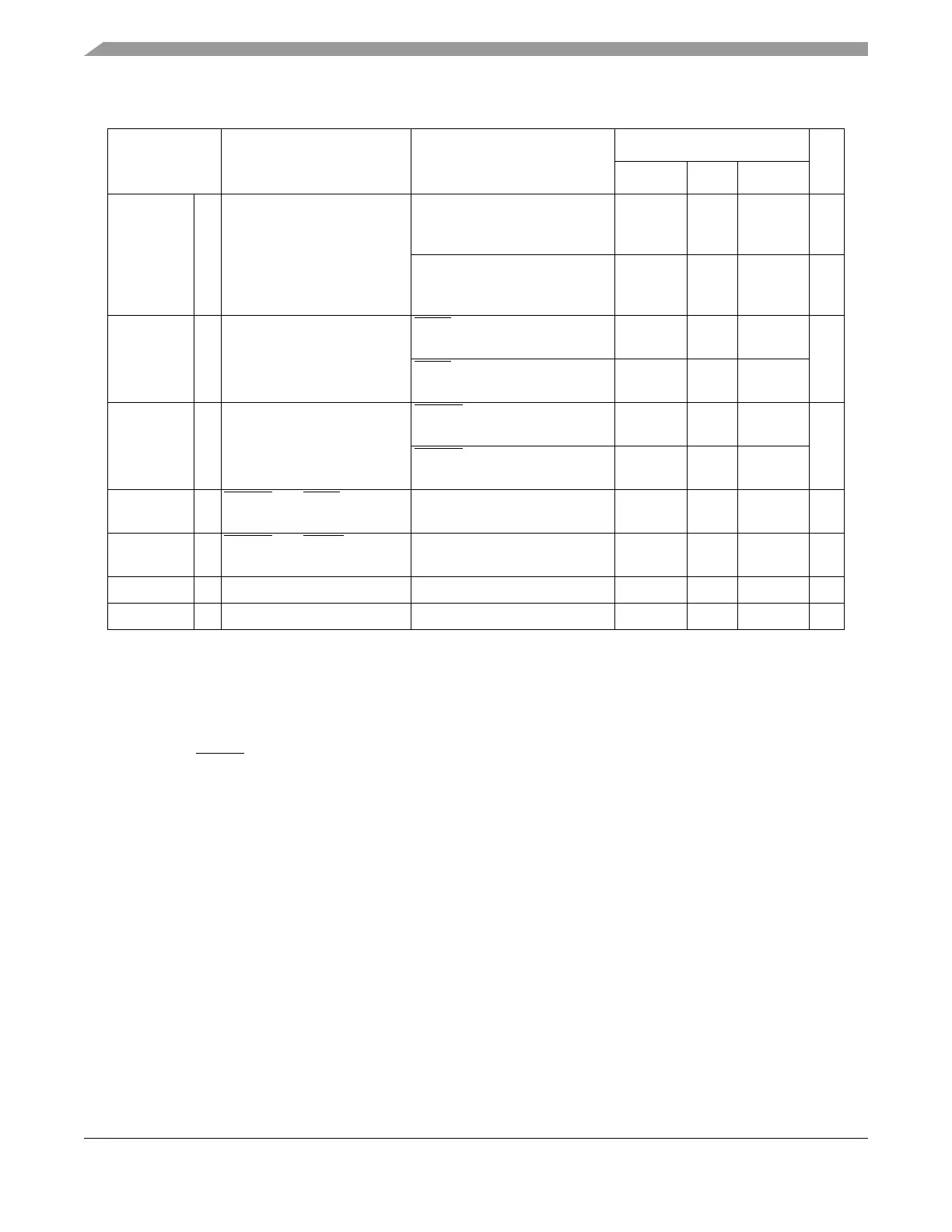
I
OL_R
CC Strong pull-down current
2
Device under power-on reset
V
DD_HV_IO
= V
DD_POR
,
V
OL
= 0.35 * V
DD_HV_IO
0.2 — — mA
Device under power-on reset
3.0 V < V
DD_HV_IO
<5.5V,
V
OL
>0.9V
11 — — mA
|I
WPU
| CC Weak pull-up current absolute
value
ESR0 pin
V
IN
= 0.69 * V
DD_HV_IO
23 — — µA
ESR0
pin
V
IN
= 0.49 * V
DD_HV_IO
——82
|I
WPD
| CC Weak pull-down current
absolute value
PORST pin
V
IN
= 0.69 * V
DD_HV_IO
——130µA
PORST
pin
V
IN
= 0.49 * V
DD_HV_IO
40 — —
W
FRST
SR PORST and ESR0 input
filtered pulse
— — — 500 ns
W
NFRST
SR PORST and ESR0 input not
filtered pulse
— 2000 — — ns
W
FNMI
SR ESR1 input filtered pulse — — — 15 ns
W
NFNMI
SR ESR1 input not filtered pulse — 400 — — ns
1
An external 4.7 KOhm pull-up resistor is recommended to be used with the PORST and ESR0 pins for fast negation
of the signals.
2
I
OL_R
applies to both PORST and ESR0: Strong pull-down is active on PHASE0 for PORST. Strong pull-down is active
on PHASE0, PHASE1, PHASE2, and the beginning of PHASE3 for ESR0.
Table 20. Reset electrical characteristics (continued)
Symbol Parameter Conditions
Value
1
Unit
Min Typ Max

 Loading...


