MPC5777M Microcontroller Data Sheet, Rev. 6
Electrical characteristics
NXP Semiconductors76
3.14.4 Device voltage monitoring
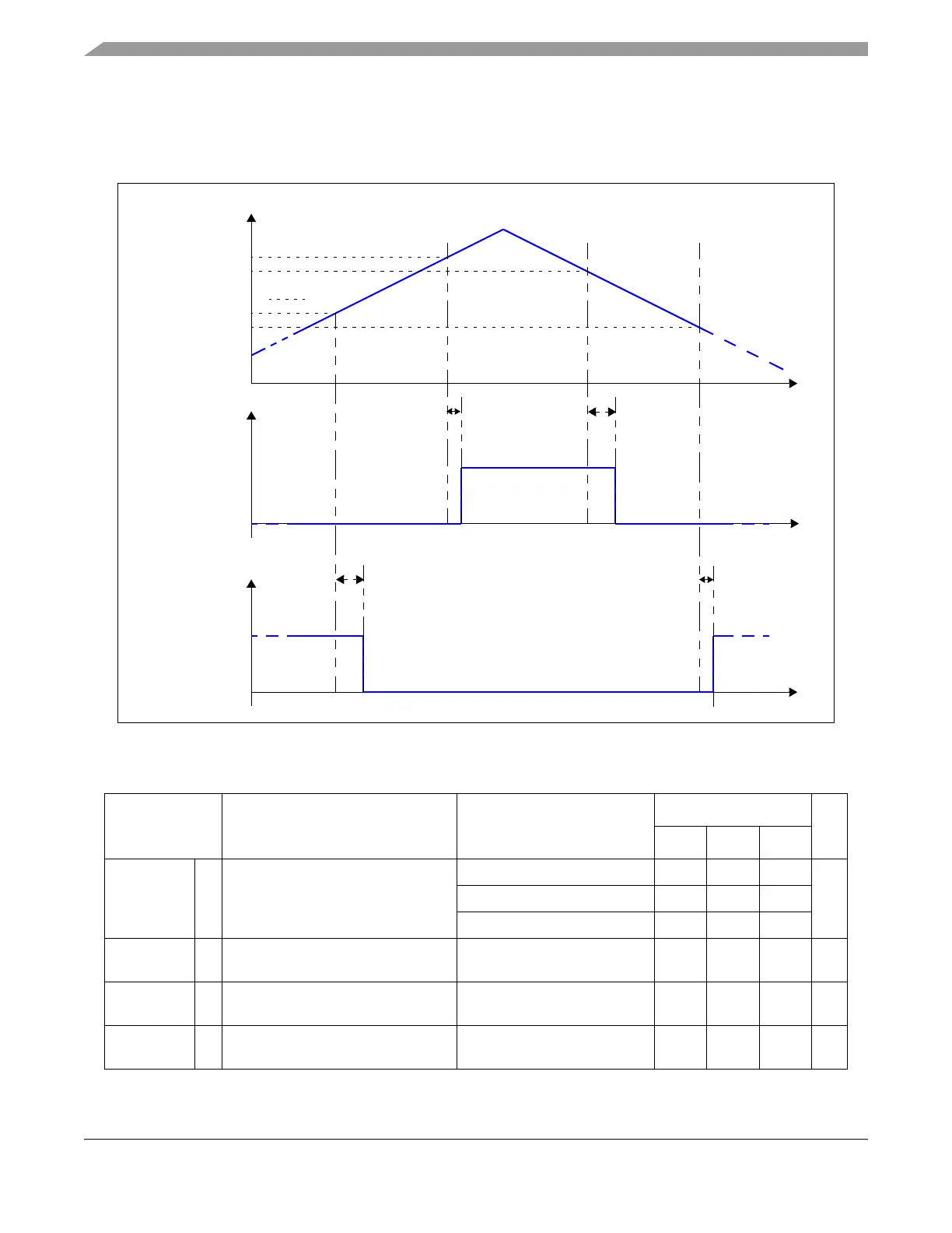
The LVD/HVDs and their associated levels for the device are given in the following table. The figure below illustrates the
workings of voltage monitoring threshold.
Figure 21. Voltage monitor threshold definition
Table 37. Voltage monitor electrical characteristics
1
Symbol Parameter Conditions
Value
Unit
Min Typ Max
V
PORUP_LV
2
CC LV supply power on reset threshold Rising voltage (power up) 1111 — 1235 mV
Falling voltage (power down)
3
1015 — 1125
Hysteresis on power-up 50 — —
V
LVD096
CC LV internal
4
supply low voltage
monitoring
See note
5
1015 — 1145 mV
V
LVD108
CC Core LV internal
4
supply low voltage
monitoring
See note
6
1150 — 1220 mV
V
LVD112
CC LV external
7
supply low voltage
monitoring
See note
5
1175 — 1235 mV
V
DD_xxx
V
LVD(fall)
HVD TRIGGER
t
VDRELEASE
V
LVD(rise)
t
VDASSERT
V
HVD(fall)
V
HVD(rise)
LVD TRIGGER
t
VDRELEASE
t
VDASSERT
(INTERNAL)
(INTERNAL)

 Loading...


