Electrical characteristics
MPC5777M Microcontroller Data Sheet, Rev. 6
NXP Semiconductors 77
V
HVD140
CC LV external
10
supply high voltage
monitoring
See note
8
1385 — 1475 mV
V
HVD145
CC LV externa
10
supply high voltage
reset threshold
— 1430 — 1510 mV
V
PORUP_HV
2
CC HV supply power on reset threshold
9
Rising voltage (power up) on
PMC/IO Main supply
4040 — 4480
10
mV
Rising voltage (power up) on
IO JTAG and Osc supply
2730 — 3030
Rising voltage (power up) on
ADC supply
2870 — 3182
Falling voltage (power down)
11
2850 — 3162
Hysteresis on power up
12
878 — 1630
V
POR240
CC HV supply power-on reset voltage
monitoring
Rising voltage 2420 — 2780 mV
Falling voltage 2400 — 2760
V
LVD270
CC HV supply low voltage monitoring Rising voltage 2750 — 3000 mV
Falling voltage 2700 — 2950
V
LVD295
CC Flash supply low voltage
monitoring
13
Rising voltage — — 3120 mV
Falling voltage 2920 — 3100
V
HVD360
CC Flash supply high voltage monitoring Rising voltage 3435 — 3650 mV
Falling voltage 3415 — —
V
LVD360
CC HV supply low voltage monitoring Rising voltage — — 4000 mV
Falling voltage 3600 — 3880
V
LVD400
CC HV supply low voltage monitoring Rising voltage 4110 — 4410 mV
Falling voltage 3970 — 4270
V
HVD600
CC HV supply high voltage monitoring Rising voltage 5560 — 5960 mV
Falling voltage 5500 — 5900
t
VDASSERT
CC Voltage detector threshold crossing
assertion
—0.1—2µs
t
VDRELEASE
CC Voltage detector threshold crossing
de-assertion
—5—20µs
1
For V
DD_LV
levels, a maximum of 30 mV IR drop is incurred from the pin to all sinks on the die. For other LVD, the IR
drop is estimated by multiplying the supply current by 0.5 .
2
V
PORUP_LV
and V
PORUP_HV
threshold are untrimmed values before completion of the power-up sequence. All other
LVD/HVD thresholds are provided after trimming.
3
Assume all of LVDs on LV supplies disabled.
4
LV internal supply levels are measured on device internal supply grid after internal voltage drop.
5
LVD is released after t
VDRELEASE
temporization when upper threshold is crossed, LVD is asserted t
VDASSERT
after
detection when lower threshold is crossed.
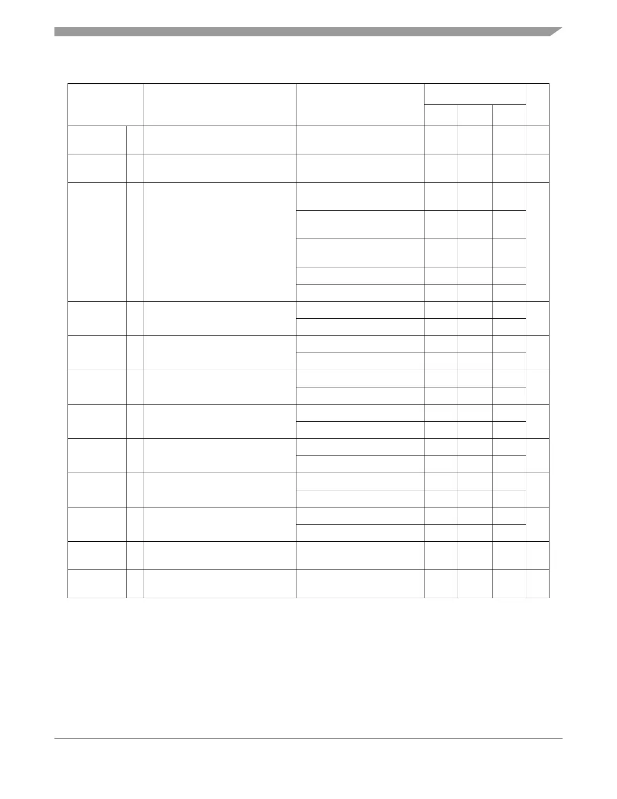
Table 37. Voltage monitor electrical characteristics
1
(continued)
Symbol Parameter Conditions
Value
Unit
Min Typ Max

 Loading...


