44473001TH Rev.1
111 /
Oki Data CONFIDENTIAL
4.REPLACEMENT OF PARTS
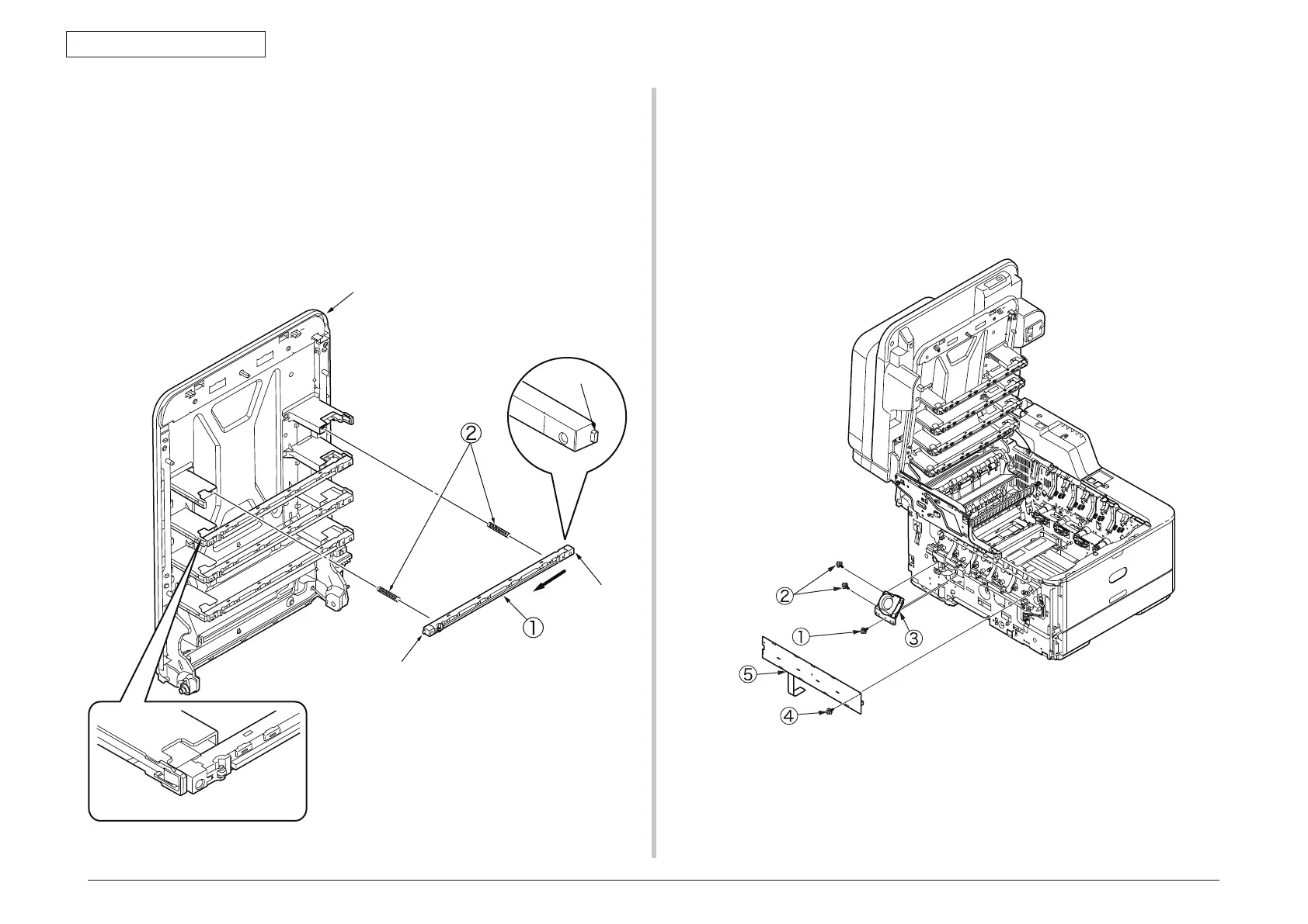
4.2.10 LED assembly. and LED assembly springs
(1) Open the Scanner and the top cover.
(2) Remove the cables of the LED assembly. As shown in diagram (2), apply force in
the direction of the arrow to unlatch the portion A and then the portion B to detach
the LED assembly
① .
(3
) Turning the LED assembly springs
②
clockwise, detach it.
Latch B
Latch A
Top cover
Diagram (1)
Diagram (2)
Latch A
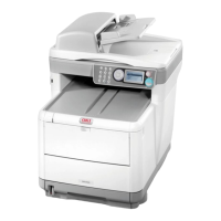
4.2.11 Image drum fan and ZHJ board
(1) Remove the left side cover. (See 4.2.3)
(2) Remove the (silver-colored) screw
①
and the two (silver-colored) screws to detach
the image drum fan
③ .
(3
) Remove the (silver-colored) screw
④
and unlatch five portions to detach the ZHJ
board
⑤ .