44473001TH Rev.1
118 /
Oki Data CONFIDENTIAL
4.REPLACEMENT OF PARTS
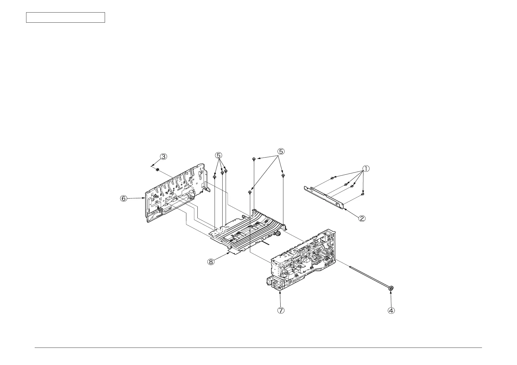
4.2.19 Side-L assembly, side-R assembly and base
assembly
(1) Remove the left side cover, the right side cover, the rear cover, the top cover
assembly, the operator panel assembly, the feeder assembly, the guide-ejection
assembly and the registration assembly.
(2 Remove the four (silver-colored) screws
①
to remove the plate-bottom
②
.
(3
) Remove the E-shaped retainer ring
③
and then the shaft
④
.
(4
) Remove the six (silver-colored) screws
⑤
to detach the side-L assembly
⑥
, the
side-R assembly
⑦
and the base assembly
⑧
.