DMTA-20006-01EN, Rev. B, February 2014
Chapter 2
30
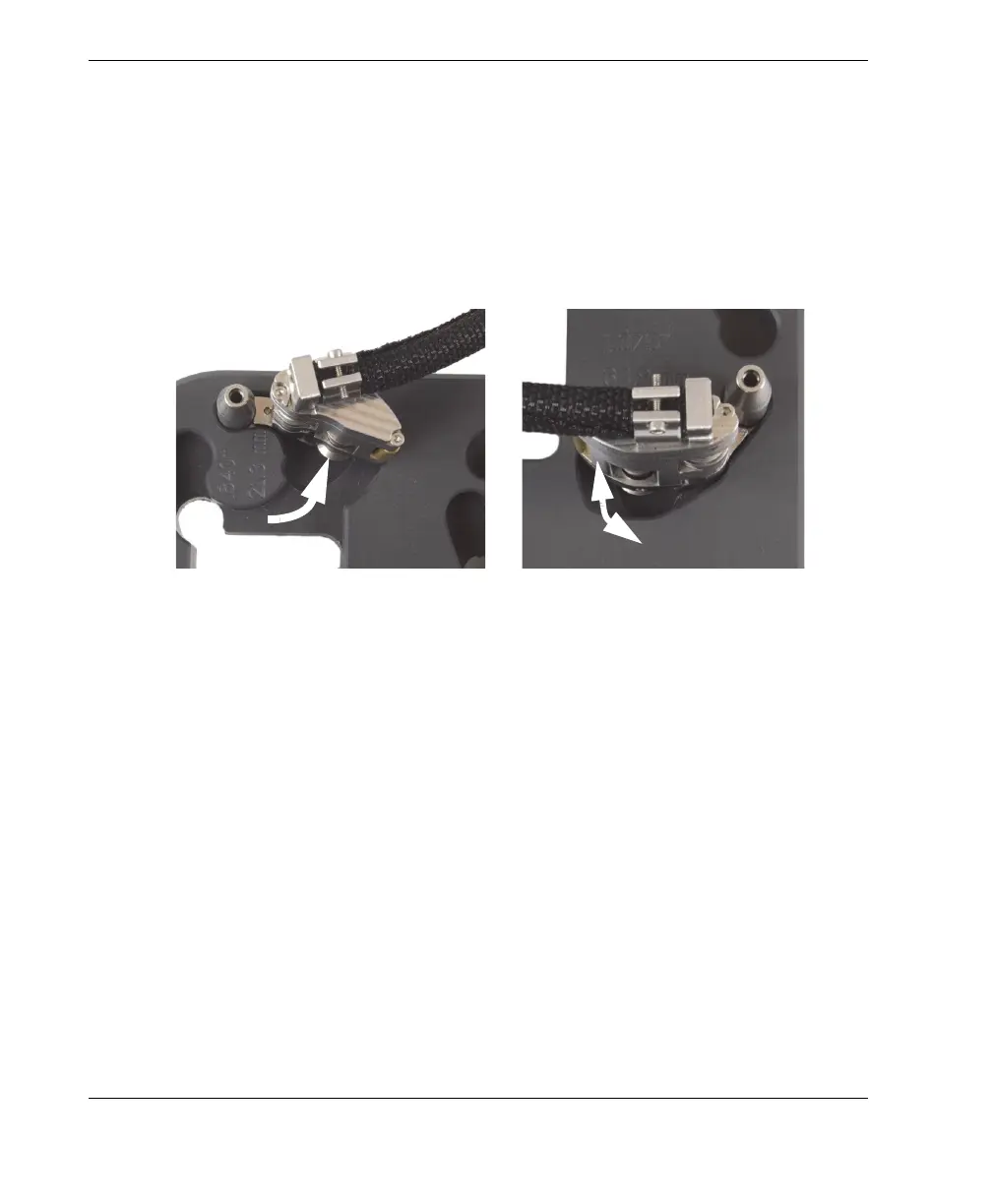
d) For the smallest outside diameters (21.3 mm to 33.4 mm [0.840 in. to
1.315 in.]), rotate the tail outward, as far as possible, so that the tail wheel is
positioned farthest from the center of the setup pattern (see Figure 2-10 on
page 30).
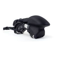
e) For all larger diameters (33.4 mm to 114.3 mm [1.315 in. to 4.500 in.]), first
fully rotate the tail outward, and then fully inward, so that the tail wheel is
positioned closest to the center of the setup pattern with the correct spring
load (see in Figure 2-10 on page 30).
Figure 2-10 Rotating the tail to the initial position
4. If a half-link is required for the particular scanner configuration (see Figure 2-11
on page 31):
a) On the setup template, install a half-link onto the tail.
b) Tighten the half-link pivot screw until snug, and then loosen one turn.
For pipe OD smaller than 33.4 .mm (1.315 in.)
For pipe OD larger than 33.4 mm (1.315 in.)
1-Outward
2-Inward