DMTA-20006-01EN, Rev. B, February 2014
Chapter 2
38
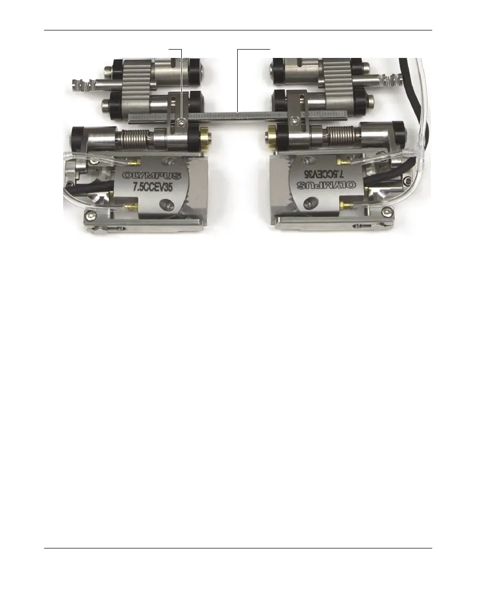
Figure 2-21 The graduated crossbar
5. Determine how to configure the scanner:
a) Determine the real outside diameter of the pipe to be inspected. Do not
assume that the nominal diameter is the real outside diameter.
b) Refer to the scanner setup chart to note tail setting, the probe-holder position,
as well as the number and type of links required for the outside diameter of
the pipe to be inspected (see Table 15 on page 65 for pipe OD smaller than
2.50 in., and Table 16 on page 66 for pipe OD larger than 2.50 in.).
c) See Table 7 on page 55 to select the appropriate wedge for the outside
diameter of the pipe to be inspected.
6. As required for your configuration, add or remove links by completely loosening
the pivot screws.
7. Adjust the length of the exposed cables and tubes as needed (see
section “Adjusting the Length of Exposed Cables and Tubes” on page 26 for
details).
8. Adjust the tail length as follows:
a) Loosen the tail-adjustment screw, and then slide the tail to the appropriate
setting.
The tail setting numbers correspond with the notches on the tail (see
Figure 2-22 on page 39).
Graduated crossbarCrossbar screw