DMTA-20006-01EN, Rev. B, February 2014
Chapter 2
32
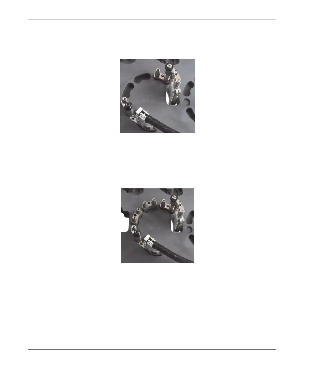
e) Insert the probe-holder assembly into its setup template pocket. If required,
bend the slip joint by hand until the assembly fits loosely into the setup
template (see Figure 2-13 on page 32).
Figure 2-13 Installing the probe holder into the setup template
6. On the setup template, install the required male links or long links into their
respective pockets (see Figure 2-14 on page 32).
Figure 2-14 Installing male links
7. On the setup template, install the required female links and/or medium links onto
the links, lightly tighten all the pivot screws, and while holding down the scanner