DMTA-20006-01EN, Rev. B, February 2014
Chapter 2
42
Figure 2-25 Placing the wedge-separation indicator
4. Tighten the wedge-separation indicator screw(s).
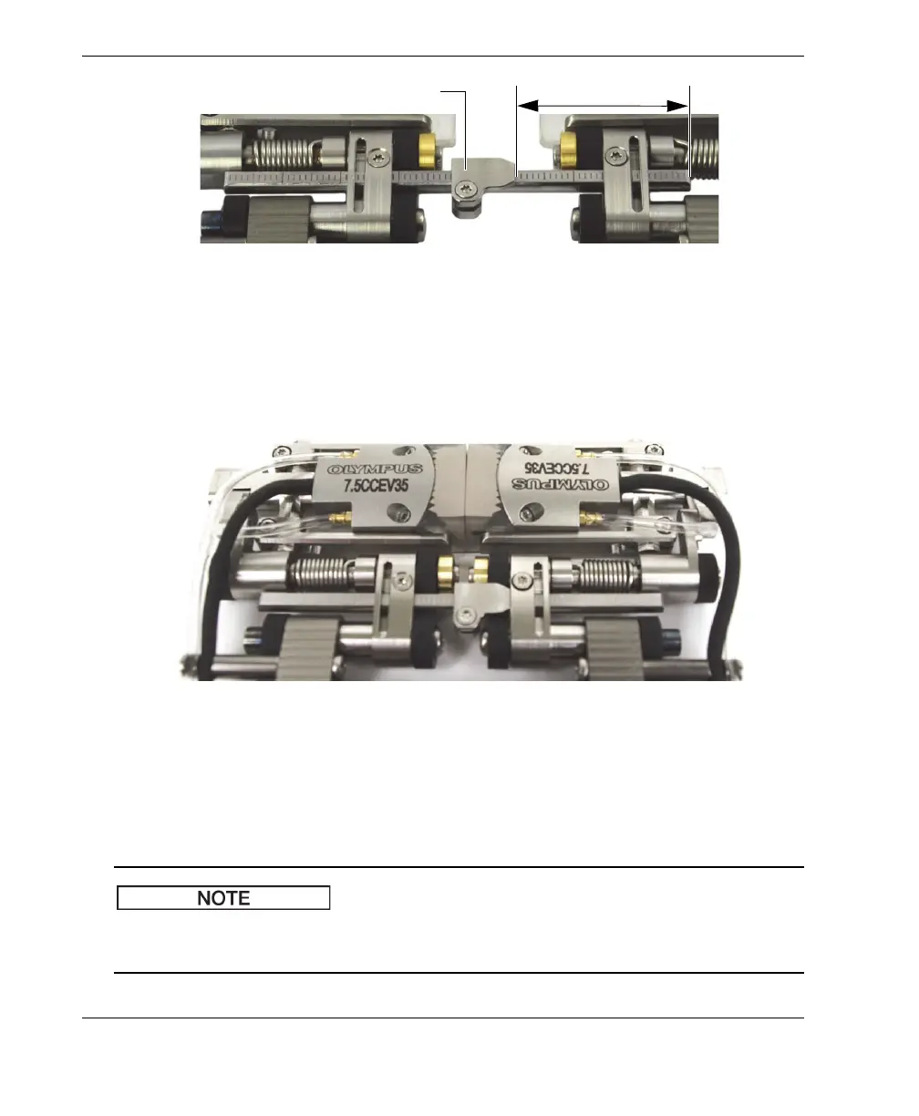
5. Slide both sides of the scanner together until the wedge faces touch each other
(see Figure 2-26 on page 42).
Figure 2-26 Bringing the wedge faces together
6. Slide the crossbar(s) to the right so that the wedge-separation indicator(s) makes
contact with the right hand link (see Figure 2-26 on page 42).
7. Ensure the scanner sides remain parallel.
When the scanner configuration uses two crossbars, use the graduations to ensure
that the distance between the two scanner sides is the same for both crossbars.
Wedge-separation indicator
n
th
major graduations